Buildings.Fluid.DXSystems.Heating.BaseClasses
Package with base classes for Buildings.Fluid.DXSystems.Heating
Information
This package contains base classes that are used to construct the models in Buildings.Fluid.DXSystems.Heating.
Extends from Modelica.Icons.BasesPackage (Icon for packages containing base classes).
Package Content
| Name | Description |
|---|---|
| Calculates defrost curve value at given temperature and mass flow rate | |
| Calculates defrost curve value at given temperature and mass flow rate | |
| Partial model for DX heating coil | |
| Package with base classes for DX heating coils |
 Buildings.Fluid.DXSystems.Heating.BaseClasses.CoilDefrostTimeCalculations
Calculates defrost curve value at given temperature and mass flow rate

Information
Block that calculates the defrost cycling time fraction tDefFra,
the heating capacity multiplier heaCapMul
and the input power multiplier inpPowMul.
The inputs are the measured
temperature TOut and humidity ratio per kg total air XOut
of the outdoor air.
The calculation is based on Section 15.2.11.4 in the EnergyPlus 22.2
engineering reference
document and is as decribed below.
Calculations
The model first estimates the outdoor coil temperature TCoiOut from
the outdoor air drybulb temperature TOut using
TCoiOut = 0.82*TOut - 8.589.
The difference between the outdoor air humidity ratio XOutDryAir and
the saturated air humidity ratio at outdoor coil temperature is used to determine
frost formation on the outdoor coil as
delta_XCoilOut = max(1e-6, (XOutDryAir - XSatOutCoil)).
The block then calculates the time period fraction tDefFra for which
the defrost operation is assumed to run, based on defrost calculation mode specified
by the parameter defTri.
In the EnergyPlus model, tDefFra represents the fraction of the constant
timestep in the simulation model for which the defrost operation is assumed to be
active. This is calculated to be a higher value when the outdoor air temperature
is lower and the relative humidity is higher. This results in a higher proportion
of the consumed power going towards the defrost operation and lower heating of
the condenser's air stream.
In this Modelica implementation of the model, while the timestep may not be constant and may vary based on the solver for the simulation, the same assumption is used for calculating the proportion of energy consumed for defrost mode operation. The coil does not actually enter defrost operation (with reverse flow of refrigerant) during this timestep fraction.
If defTri is set to timed, tDefFra is set
to the user input parameter for defrost operation timestep fraction tDefRun.
The heating capacity multiplier heaCapMul and input power multiplier
inpPowMul are calculated as
tDefFra = tDefRun,
heaCapMul = 0.909 - 107.33*delta_XCoilOut,
inpPowMul = 0.9 - 36.45*delta_XCoilOut.
If defTri is set to onDemand, tDefFra,
heaCapMul and inpPowMul are calculated as
tDefFra = 1/(1 + (0.01446/delta_XCoilOut)),
heaCapMul = 0.875*(1 - tDefFra),
inpPowMul = 0.954*(1 - tDefFra).
Extends from Modelica.Blocks.Icons.Block (Basic graphical layout of input/output block).
Parameters
| Type | Name | Default | Description |
|---|---|---|---|
| DefrostTimeMethods | defTri | Buildings.Fluid.DXSystems.He... | Type of method to trigger the defrost cycle |
| Real | tDefRun | 0.5 | If defrost operation is timed, timestep fraction for which defrost cycle is run [1] |
| ThermodynamicTemperature | TDefLim | Maximum temperature at which defrost operation is activated [K] | |
| Advanced | |||
| TemperatureDifference | dTHys | 0.5 | Temperature comparison hysteresis difference [K] |
Connectors
| Type | Name | Description |
|---|---|---|
| input RealInput | TOut | Temperature of outdoor air [K] |
| input RealInput | XOut | Humidity ratio of outdoor air [kg/kg] |
| output RealOutput | tDefFra | Defrost operation timestep fraction [1] |
| output RealOutput | heaCapMul | Heating capacity multiplier [1] |
| output RealOutput | inpPowMul | Input power multiplier [1] |
Modelica definition
 Buildings.Fluid.DXSystems.Heating.BaseClasses.DefrostCapacity
Calculates defrost curve value at given temperature and mass flow rate

Information
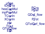
Block that calculates the heat transfered to airloop QTotDef_flow,
the total heating power consumption of the component PTot,
the defrost input power consumption PDef
and the crankcase heater input power consumption PCra.
The calculation are based on in Section 15.2.11.5 and 11.6 in the the EnergyPlus 22.2 engineering reference document, and are as
-
the defrost cycle time fraction
tDefFra, the heating capacity multiplierheaCapMuland the input power multiplierinpPowMulcalculated by Buildings.Fluid.DXSystems.Heating.BaseClasses.CoilDefrostTimeCalculations. -
the total heat transfer
QTot_flowand energy input ratioEIRcalculated by Buildings.Fluid.DXSystems.BaseClasses.DryCoil. -
the measured temperature
TConIn, humidity ratio per kg of total airXConInand pressurepInof the indoor coil inlet air temperature. -
the measured outdoor air temperature
TOut.
Calculations
Based on the type of defrost method defOpe, different calculations are used:
-
If
defOpe = reverseCycle, the heat transfer rate from the airstream to the outdoor coilQDef_flowand the power consumption for defrostPDefare calculated as follows:QDef_flow = 0.01*tDefFra*(7.222 - TOut)*(QTot_flow/1.01667),
PDef = defMod_T*(QTot_flow/1.01667)*tDefFra*RTF,where
defMod_Tis the defrost operation modifier calculated asdefMod_T = defCur[1] + defCur[2]*TConInWetBul + defCur[3]*TConInWetBul2 + defCur[4]*TOut + defCur[5]*TOut2 + defCur[6]*TOut*TConInWetBul,
and
RTFis the runtime fraction of the heating coil, calculated from part load ratioPLRand part load fractionPLFraasRTF = PLR/PLFra.
The part load ratio
PLRis set to1since only a constant speed DX heating coil is implemented.The
PLFrais calculated from the part load fraction curvedefCur.PLFraFunPLRasPLFra = PLFraFunPLR[1] + PLFraFunPLR[2]*PLR + PLFraFunPLR[3]*PLR2 + PLFraFunPLR[4]*PLR3.
-
If
defOpe = reverseCycle, the calculations areQDef_flow = 0,
PDef = QDefResCap*tDefFra*RTF,where
QDefResCapis the rated capacity of the resistive heating element on the outdoor coil.
The remaining variable calculations forRTF,PLRandPLFraare the same as above.
The total power consumption PTot and total heat flowrate to the air stream
QTotDef_flow (while accounting for defrost operation) is calculated
as follows:
PTot = QTot_flow*EIR*PLR*inpPowMul/PLFra,
QTotDef_flow = QTot_flow*heaCapMul.
Extends from Modelica.Blocks.Icons.Block (Basic graphical layout of input/output block).
Parameters
| Type | Name | Default | Description |
|---|---|---|---|
| replaceable package MediumA | Modelica.Media.Interfaces.Pa... | Fluid medium package | |
| Real | tDefRun | 0.5 | If defrost operation is timed, timestep fraction for which defrost cycle is run [1] |
| Power | QDefResCap | defCur.QDefResCap | Capacity of resistive defrost element [W] |
| DefrostTimeMethods | defTri | Buildings.Fluid.DXSystems.He... | Type of method to trigger the defrost cycle |
| DefrostOperation | defOpe | Buildings.Fluid.DXSystems.He... | Type of defrost method |
| DXCoil | defCur | Defrost curve parameter record | |
Connectors
| Type | Name | Description |
|---|---|---|
| replaceable package MediumA | Fluid medium package | |
| input RealInput | tDefFra | Calculated fraction of timestep for which the defrost cycle is assumed to run [1] |
| input RealInput | heaCapMul | Heating capacity multiplier [1] |
| input RealInput | inpPowMul | Input power multiplier [1] |
| input RealInput | TConIn | Temperature of air entering indoor condenser unit [K] |
| input RealInput | XConIn | Humidity ratio of air entering indoor condenser coil [kg/kg] |
| input RealInput | pIn | Pressure of air entering indoor condenser coil [Pa] |
| input RealInput | TOut | Temperature of outdoor air [K] |
| input RealInput | QTot_flow | Total heating capacity from heating coil curve calculations [W] |
| input RealInput | EIR | Total energy input ratio from heating coil curve calculations [1] |
| input RealInput | uSpe | Input speed signal [1] |
| output RealOutput | QDef_flow | Power extracted from airloop to defrost outdoor coil [W] |
| output RealOutput | PDef | Power input required for running defrost operation [W] |
| output RealOutput | PTot | Total power input required for running heating coil with defrost operation [W] |
| output RealOutput | QTotDef_flow | Total heat added to airloop after defrost [W] |
| output RealOutput | PCra | Crankcase heater power consumption [W] |
Modelica definition
 Buildings.Fluid.DXSystems.Heating.BaseClasses.PartialDXHeatingCoil
Partial model for DX heating coil

Information
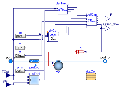
This partial model is the base class for Buildings.Fluid.DXSystems.Heating.AirSource.SingleSpeed.
Extends from Buildings.Fluid.Interfaces.TwoPortHeatMassExchanger (Partial model transporting one fluid stream with storing mass or energy).
Parameters
| Type | Name | Default | Description |
|---|---|---|---|
| replaceable package Medium | PartialMedium | Medium in the component | |
| DXCoil | datCoi | Performance data | |
| Nominal condition | |||
| MassFlowRate | m_flow_nominal | datCoi.sta[nSta].nomVal.m_fl... | Nominal mass flow rate [kg/s] |
| PressureDifference | dp_nominal | Pressure difference [Pa] | |
| Assumptions | |||
| Boolean | allowFlowReversal | true | = false to simplify equations, assuming, but not enforcing, no flow reversal |
| Advanced | |||
| MassFlowRate | m_flow_small | 1E-4*abs(m_flow_nominal) | Small mass flow rate for regularization of zero flow [kg/s] |
| TemperatureDifference | dTHys | 0.5 | Temperature comparison for hysteresis [K] |
| Diagnostics | |||
| Boolean | show_T | false | = true, if actual temperature at port is computed |
| Flow resistance | |||
| Boolean | from_dp | false | = true, use m_flow = f(dp) else dp = f(m_flow) |
| Boolean | linearizeFlowResistance | false | = true, use linear relation between m_flow and dp for any flow rate |
| Real | deltaM | 0.1 | Fraction of nominal flow rate where flow transitions to laminar |
| Dynamics | |||
| Nominal condition | |||
| Time | tau | 30 | Time constant at nominal flow (if energyDynamics <> SteadyState) [s] |
| Conservation equations | |||
| Dynamics | energyDynamics | Modelica.Fluid.Types.Dynamic... | Type of energy balance: dynamic (3 initialization options) or steady state |
| Initialization | |||
| AbsolutePressure | p_start | Medium.p_default | Start value of pressure [Pa] |
| Temperature | T_start | Medium.T_default | Start value of temperature [K] |
| MassFraction | X_start[Medium.nX] | Medium.X_default | Start value of mass fractions m_i/m [kg/kg] |
| ExtraProperty | C_start[Medium.nC] | fill(0, Medium.nC) | Start value of trace substances |
Connectors
| Type | Name | Description |
|---|---|---|
| replaceable package Medium | Medium in the component | |
| FluidPort_a | port_a | Fluid connector a (positive design flow direction is from port_a to port_b) |
| FluidPort_b | port_b | Fluid connector b (positive design flow direction is from port_a to port_b) |
| input RealInput | TOut | Outside air dry bulb temperature for an air cooled condenser or wetbulb temperature for an evaporative cooled condenser [K] |
| input RealInput | phi | Outdoor air relative humidity at evaporator inlet (0...1) [1] |
| output RealOutput | P | Electrical power consumed [W] |
| output RealOutput | QSen_flow | Sensible heat flow rate [W] |
