| Name | Description |
|---|---|
| Collection of models that illustrate model use and test models | |
| Outputs the number of signals that are above/below a certain threshold | |
| Records the time since the input changed to false | |
| PID controller with anti-windup, output limiter and output hysteresis | |
| PID controller with anti-windup, hysteresis and timer to prevent short cycling | |
| Ranks output signals such that y[i] >= y[i+1] |
 Buildings.Controls.Continuous.NumberOfRequests

Block whose output is equal to the number of inputs that exceed a threshold.
This model may be used to check how many rooms exceed a temperature threshold.
Extends from Modelica.Blocks.Interfaces.BlockIcon (Basic graphical layout of input/output block).
| Type | Name | Default | Description |
|---|---|---|---|
| Integer | nin | Number of inputs | |
| Real | threShold | 0 | Threshold |
| Integer | kind | Set to 0 for u>threShold, to 1 for >=, to 2 for <= or to 3 for < |
| Type | Name | Description |
|---|---|---|
| output IntegerOutput | y | Number of input signals that violate the threshold |
| input RealInput | u[nin] | Input signals |
block NumberOfRequests "Outputs the number of signals that are above/below a certain threshold" extends Modelica.Blocks.Interfaces.BlockIcon;parameter Integer nin "Number of inputs"; parameter Real threShold = 0 "Threshold"; parameter Integer kind "Set to 0 for u>threShold, to 1 for >=, to 2 for <= or to 3 for <"; Modelica.Blocks.Interfaces.IntegerOutput y "Number of input signals that violate the threshold"; Modelica.Blocks.Interfaces.RealInput u[nin] "Input signals"; algorithm y := 0; for i in 1:nin loop if kind == 0 then if u[i] > threShold then y := y+1; end if; end if; if kind == 1 then if u[i] >= threShold then y := y+1; end if; end if; if kind == 2 then if u[i] <= threShold then y := y+1; end if; end if; if kind == 3 then if u[i] < threShold then y := y+1; end if; end if; end for; end NumberOfRequests;
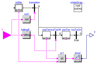
 Buildings.Controls.Continuous.OffTimer

At the beginning of the simulation, this block outputs the time that has elapsed since the start of the simulation. Afterwards, whenever its input switches to false, the timer is reset.
Extends from Modelica.Blocks.Interfaces.partialBooleanBlockIcon (Basic graphical layout of logical block).
| Type | Name | Description |
|---|---|---|
| input BooleanInput | u | Connector of Boolean input signal |
| output RealOutput | y | Connector of Real output signal |
model OffTimer "Records the time since the input changed to false" extends Modelica.Blocks.Interfaces.partialBooleanBlockIcon;Modelica.Blocks.Interfaces.BooleanInput u "Connector of Boolean input signal"; Modelica.Blocks.Interfaces.RealOutput y "Connector of Real output signal"; protected Modelica.Blocks.Logical.Timer timer; Modelica.StateGraph.InitialStepWithSignal iniSte; Modelica.StateGraph.TransitionWithSignal transition(enableTimer=false); Modelica.StateGraph.StepWithSignal staTim(nIn=2); Modelica.StateGraph.StepWithSignal stoTim; Modelica.StateGraph.TransitionWithSignal traToOff; Modelica.StateGraph.Transition traToOn(enableTimer=false) "Transition to on"; inner Modelica.StateGraph.StateGraphRoot stateGraphRoot; Modelica.Blocks.Logical.Not not1; Modelica.Blocks.Logical.Or or1; Modelica.Blocks.Logical.FallingEdge fallingEdge; equationconnect(stoTim.outPort[1], traToOn.inPort); connect(iniSte.outPort[1], transition.inPort); connect(staTim.outPort[1], traToOff.inPort); connect(traToOff.outPort, stoTim.inPort[1]); connect(transition.outPort, staTim.inPort[1]); connect(u, not1.u); connect(timer.y, y); connect(not1.y, transition.condition); connect(u, fallingEdge.u); connect(fallingEdge.y, traToOff.condition); connect(iniSte.active, or1.u2); connect(staTim.active, or1.u1); connect(or1.y, timer.u); connect(traToOn.outPort, staTim.inPort[2]); end OffTimer;
 Buildings.Controls.Continuous.PIDHysteresis

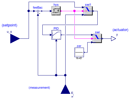
Block of a controller for set point tracking with a hysteresis element that switches the controller on and off.
If the controller is off, and the control error becomes larger than eOn, then the controller switches to on and remains on until the control error is smaller than eOff. When the controller is on, the set point tracking can be done using a P-, PI-, or PID-controller. In its off-mode, the control output is zero. Thus, the parameters yMin and yMax are used to constrain the output of the controller during its on mode only. This can be used, for example, to modulate a device between 0.3 and 1.0, and switch it to off when the control error is small enough.
Extends from Modelica.Blocks.Interfaces.SVcontrol (Single-Variable continuous controller).
| Type | Name | Default | Description |
|---|---|---|---|
| Hysteresis | |||
| Real | eOn | 1 | if off and control error > eOn, switch to set point tracking |
| Real | eOff | -eOn | if on and control error < eOff, set y=0 |
| Boolean | pre_y_start | false | Value of hysteresis output at initial time |
| Set point tracking | |||
| SimpleController | controllerType | Modelica.Blocks.Types.Simple... | Type of controller |
| Real | k | 1 | Gain of controller |
| Time | Ti | Time constant of Integrator block [s] | |
| Time | Td | Time constant of Derivative block [s] | |
| Real | yMax | 1 | Upper limit of output |
| Real | yMin | 0 | Lower limit of output |
| Real | wp | 1 | Set-point weight for Proportional block (0..1) |
| Real | wd | 0 | Set-point weight for Derivative block (0..1) |
| Real | Ni | 0.9 | Ni*Ti is time constant of anti-windup compensation |
| Real | Nd | 10 | The higher Nd, the more ideal the derivative block |
| Initialization | |||
| InitPID | initType | Modelica.Blocks.Types.InitPI... | Type of initialization (1: no init, 2: steady state, 3: initial state, 4: initial output) |
| Boolean | limitsAtInit | true | = false, if limits are ignored during initializiation |
| Real | xi_start | 0 | Initial or guess value value for integrator output (= integrator state) |
| Real | xd_start | 0 | Initial or guess value for state of derivative block |
| Real | y_start | 0 | Initial value of output |
| Type | Name | Description |
|---|---|---|
| input RealInput | u_s | Connector of setpoint input signal |
| input RealInput | u_m | Connector of measurement input signal |
| output RealOutput | y | Connector of actuator output signal |
model PIDHysteresis
  "PID controller with anti-windup, output limiter and output hysteresis"
  extends Modelica.Blocks.Interfaces.SVcontrol;

  parameter Real eOn = 1
    "if off and control error > eOn, switch to set point tracking";
  parameter Real eOff = -eOn "if on and control error < eOff, set y=0";
  parameter Boolean pre_y_start=false
    "Value of hysteresis output at initial time";

  parameter Modelica.Blocks.Types.SimpleController controllerType=Modelica.Blocks.Types.SimpleController.PID
    "Type of controller";
  parameter Real k=1 "Gain of controller";
  parameter Modelica.SIunits.Time Ti "Time constant of Integrator block";
  parameter Modelica.SIunits.Time Td "Time constant of Derivative block";
  parameter Real yMax=1 "Upper limit of output";
  parameter Real yMin=0 "Lower limit of output";
  parameter Real wp=1 "Set-point weight for Proportional block (0..1)";
  parameter Real wd=0 "Set-point weight for Derivative block (0..1)";
  parameter Real Ni=0.9 "Ni*Ti is time constant of anti-windup compensation";
  parameter Real Nd=10 "The higher Nd, the more ideal the derivative block";
  parameter Modelica.Blocks.Types.InitPID initType=Modelica.Blocks.Types.InitPID.DoNotUse_InitialIntegratorState
    "Type of initialization (1: no init, 2: steady state, 3: initial state, 4: initial output)";
  parameter Boolean limitsAtInit=true
    "= false, if limits are ignored during initializiation";
  parameter Real xi_start=0
    "Initial or guess value value for integrator output (= integrator state)";
  parameter Real xd_start=0
    "Initial or guess value for state of derivative block";
  parameter Real y_start=0 "Initial value of output";

  Modelica.Blocks.Continuous.LimPID PID(
    controllerType=controllerType,
    k=k,
    Ti=Ti,
    yMax=yMax,
    yMin=yMin,
    wp=wp,
    wd=wd,
    Ni=Ni,
    Nd=Nd,
    initType=initType,
    limitsAtInit=limitsAtInit,
    xi_start=xi_start,
    xd_start=xd_start,
    y_start=y_start,
    Td=Td) "Controller for room temperature";
  Modelica.Blocks.Logical.Hysteresis hys(
    pre_y_start=pre_y_start,
    uLow=eOff,
    uHigh=eOn) "Hysteresis element to switch controller on and off";
  Modelica.Blocks.Logical.Switch swi;
  Modelica.Blocks.Sources.Constant zer(k=0) "Zero signal";
  Modelica.Blocks.Math.Feedback feeBac;
  Modelica.Blocks.Logical.Switch swi1;
equation
  assert(eOff < eOn, "Wrong controller parameters. Require eOff < eOn.");
  connect(zer.y, swi.u3);
  connect(swi.y, y);
  connect(u_m, PID.u_m);
  connect(hys.y, swi.u2);
  connect(PID.y, swi.u1);
  connect(u_s, feeBac.u1);
  connect(u_m, feeBac.u2);
  connect(feeBac.y, hys.u);
  connect(u_s, swi1.u1);
  connect(hys.y, swi1.u2);
  connect(u_m, swi1.u3);
  connect(swi1.y, PID.u_s);
end PIDHysteresis;
 Buildings.Controls.Continuous.PIDHysteresisTimer

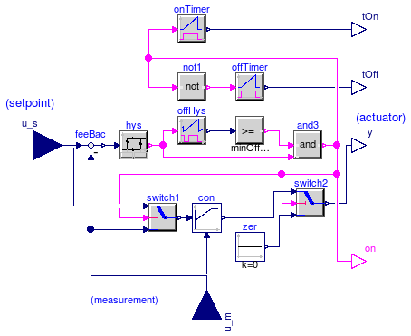
Block of a controller for set point tracking with a hysteresis element that switches the controller on and off, and a timer that prevents the controller to short cycle.
The controller is similar to Buildings.Controls.Continuous.PIDHysteresis but in addition, it has a timer that prevents the controller from switching to on too fast. When the controller switches off, the timer starts and avoids the controller from switching on until minOffTime seconds elapsed.
Extends from Modelica.Blocks.Interfaces.SVcontrol (Single-Variable continuous controller).
| Type | Name | Default | Description |
|---|---|---|---|
| On/off controller | |||
| Real | minOffTime | 600 | Minimum time that devices needs to be off before it can run again |
| Real | eOn | 1 | if off and control error > eOn, switch to set point tracking |
| Real | eOff | -eOn | if on and control error < eOff, set y=0 |
| Boolean | pre_y_start | false | Value of hysteresis output at initial time |
| Set point tracking | |||
| SimpleController | controllerType | Modelica.Blocks.Types.Simple... | Type of controller |
| Real | k | 1 | Gain of controller |
| Time | Ti | Time constant of Integrator block [s] | |
| Time | Td | Time constant of Derivative block [s] | |
| Real | yMax | 1 | Upper limit of modulating output |
| Real | yMin | 0.3 | Lower limit of modulating output (before switch to 0) |
| Real | wp | 1 | Set-point weight for Proportional block (0..1) |
| Real | wd | 0 | Set-point weight for Derivative block (0..1) |
| Real | Ni | 0.9 | Ni*Ti is time constant of anti-windup compensation |
| Real | Nd | 10 | The higher Nd, the more ideal the derivative block |
| Initialization | |||
| InitPID | initType | Modelica.Blocks.Types.InitPI... | Type of initialization (1: no init, 2: steady state, 3: initial state, 4: initial output) |
| Boolean | limitsAtInit | true | = false, if limits are ignored during initializiation |
| Real | xi_start | 0 | Initial or guess value value for integrator output (= integrator state) |
| Real | xd_start | 0 | Initial or guess value for state of derivative block |
| Real | y_start | 0 | Initial value of output |
| Type | Name | Description |
|---|---|---|
| input RealInput | u_s | Connector of setpoint input signal |
| input RealInput | u_m | Connector of measurement input signal |
| output RealOutput | y | Connector of actuator output signal |
| output RealOutput | tOn | Time since boiler switched on |
| output RealOutput | tOff | Time since boiler switched off |
| output BooleanOutput | on | Outputs true if boiler is on |
model PIDHysteresisTimer "PID controller with anti-windup, hysteresis and timer to prevent short cycling" extends Modelica.Blocks.Interfaces.SVcontrol;parameter Real minOffTime=600 "Minimum time that devices needs to be off before it can run again"; parameter Real eOn = 1 "if off and control error > eOn, switch to set point tracking"; parameter Real eOff = -eOn "if on and control error < eOff, set y=0"; parameter Boolean pre_y_start=false "Value of hysteresis output at initial time"; parameter Modelica.Blocks.Types.SimpleController controllerType=Modelica.Blocks.Types.SimpleController.PID "Type of controller"; parameter Real k=1 "Gain of controller"; parameter Modelica.SIunits.Time Ti "Time constant of Integrator block"; parameter Modelica.SIunits.Time Td "Time constant of Derivative block"; parameter Real yMax=1 "Upper limit of modulating output"; parameter Real yMin=0.3 "Lower limit of modulating output (before switch to 0)"; parameter Real wp=1 "Set-point weight for Proportional block (0..1)"; parameter Real wd=0 "Set-point weight for Derivative block (0..1)"; parameter Real Ni=0.9 "Ni*Ti is time constant of anti-windup compensation"; parameter Real Nd=10 "The higher Nd, the more ideal the derivative block"; parameter Modelica.Blocks.Types.InitPID initType=Modelica.Blocks.Types.InitPID.DoNotUse_InitialIntegratorState "Type of initialization (1: no init, 2: steady state, 3: initial state, 4: initial output)"; parameter Boolean limitsAtInit=true "= false, if limits are ignored during initializiation"; parameter Real xi_start=0 "Initial or guess value value for integrator output (= integrator state)"; parameter Real xd_start=0 "Initial or guess value for state of derivative block"; parameter Real y_start=0 "Initial value of output"; Modelica.Blocks.Interfaces.RealOutput tOn "Time since boiler switched on"; Modelica.Blocks.Interfaces.RealOutput tOff "Time since boiler switched off"; Modelica.Blocks.Continuous.LimPID con( controllerType=controllerType, k=k, Ti=Ti, Td=Td, wp=wp, wd=wd, Ni=Ni, Nd=Nd, initType=initType, limitsAtInit=limitsAtInit, xi_start=xi_start, xd_start=xd_start, y_start=y_start, final yMin=yMin, final yMax=yMax) "Controller to track setpoint"; protected Modelica.Blocks.Sources.Constant zer(k=0) "Zero signal"; Modelica.Blocks.Logical.Switch switch2; Modelica.Blocks.Logical.GreaterEqualThreshold greaterEqualThreshold(threshold= minOffTime); Modelica.Blocks.Logical.And and3; public OffTimer offHys; Modelica.Blocks.Logical.Timer onTimer; protected Modelica.Blocks.Logical.Not not1; public Modelica.Blocks.Logical.Timer offTimer; Modelica.Blocks.Interfaces.BooleanOutput on "Outputs true if boiler is on"; protected Modelica.Blocks.Logical.Switch switch1; public Modelica.Blocks.Math.Feedback feeBac; Modelica.Blocks.Logical.Hysteresis hys( pre_y_start=pre_y_start, uLow=eOff, uHigh=eOn) "Hysteresis element to switch controller on and off"; equationconnect(u_m, con.u_m); connect(zer.y,switch2. u3); connect(switch2.y, y); connect(and3.y,switch2. u2); connect(greaterEqualThreshold.y, and3.u1); connect(offHys.y, greaterEqualThreshold.u); connect(con.y,switch2. u1); connect(onTimer.y, tOn); connect(offTimer.y, tOff); connect(and3.y, on); connect(and3.y, onTimer.u); connect(and3.y, not1.u); connect(not1.y, offTimer.u); connect(and3.y, switch1.u2); connect(u_s, switch1.u1); connect(u_m, switch1.u3); connect(switch1.y, con.u_s); connect(u_s, feeBac.u1); connect(u_m, feeBac.u2); connect(feeBac.y, hys.u); connect(hys.y, offHys.u); connect(hys.y, and3.u2); end PIDHysteresisTimer;
 Buildings.Controls.Continuous.SignalRanker

Block that sorts the input signal u[:] such that the output signal satisfies y[i] >= y[i+1] for all i=1, ..., nin-1.
This block may for example be used in a variable air volume flow controller to access the position of the dampers that are most open.
Extends from Modelica.Blocks.Interfaces.MIMO (Multiple Input Multiple Output continuous control block).
| Type | Name | Default | Description |
|---|---|---|---|
| Integer | nin | 1 | Number of inputs |
| Integer | nout | nin | Number of outputs |
| Type | Name | Description |
|---|---|---|
| input RealInput | u[nin] | Connector of Real input signals |
| output RealOutput | y[nout] | Connector of Real output signals |
block SignalRanker "Ranks output signals such that y[i] >= y[i+1]" extends Modelica.Blocks.Interfaces.MIMO(final nout=nin);protected Real t "Temporary variable"; algorithm y[:] := u[:]; for i in 1:nin loop for j in 1:nin-1 loop if y[j] < y[j+1] then t := y[j+1]; y[j+1] := y[j]; y[j] := t; end if; end for; end for; // check algorithm (during development only) for i in 1:nin-1 loop assert(y[i] >= y[i+1], "Error in sorting algorithm."); end for; end SignalRanker;