| Name | Description |
|---|---|
| Header for a heat exchanger register | |
| Register for a heat exchanger | |
| Manifold for a heat exchanger air duct connection | |
| Duct manifold without resistance | |
| Collection of models that illustrate model use and test models | |
| Sensible convective heat transfer model for air to water coil | |
| Element of a heat exchanger | |
| Block to compute the latent heat transfer based on the Lewis number | |
| Partial manifold for heat exchanger duct connection | |
| Partial heat exchanger duct and pipe manifold | |
| Partial pipe manifold for a heat exchanger | |
| Pipe manifold for a heat exchanger connection | |
| Manifold for heat exchanger register |
 Buildings.HeatExchangers.BaseClasses.CoilHeader

Header for a heat exchanger coil.
This model connects the flow between its ports without modeling flow friction. Currently, the ports are connected without redistributing the flow. In latter versions, the model may be changed to define different flow reroutings in the coil header.
| Type | Name | Default | Description |
|---|---|---|---|
| replaceable package Medium | PartialMedium | Medium in the component | |
| Integer | nPipPar | Number of parallel pipes in each register | |
| Initialization | |||
| MassFlowRate | mStart_flow_a | Guess value for mass flow rate at port_a [kg/s] | |
| Advanced | |||
| Temp | flowDirection | Modelica_Fluid.Types.FlowDir... | Unidirectional (port_a -> port_b) or bidirectional flow component |
| Type | Name | Description |
|---|---|---|
| FluidPort_a | port_a[nPipPar] | Fluid connector a for medium (positive design flow direction is from port_a to port_b) |
| FluidPort_b | port_b[nPipPar] | Fluid connector b for medium (positive design flow direction is from port_a to port_b) |
model CoilHeader "Header for a heat exchanger register"
  extends Buildings.BaseClasses.BaseIcon;
  extends Buildings.Fluids.Interfaces.PartialSingleFluidParameters;

  parameter Integer nPipPar(min=1) "Number of parallel pipes in each register";
  parameter Modelica.SIunits.MassFlowRate mStart_flow_a
    "Guess value for mass flow rate at port_a";

  Modelica_Fluid.Interfaces.FluidPort_a port_a[nPipPar](
        redeclare each final package Medium = Medium,
        each m_flow(start=mStart_flow_a/nPipPar, min=if allowFlowReversal then -Modelica.Constants.inf else 0))
    "Fluid connector a for medium (positive design flow direction is from port_a to port_b)";

  Modelica_Fluid.Interfaces.FluidPort_b port_b[nPipPar](
        redeclare each final package Medium = Medium,
        each m_flow(start=-mStart_flow_a/nPipPar, max=if allowFlowReversal then +Modelica.Constants.inf else 0))
    "Fluid connector b for medium (positive design flow direction is from port_a to port_b)";

equation
  connect(port_a, port_b);
end CoilHeader;
 Buildings.HeatExchangers.BaseClasses.CoilRegister
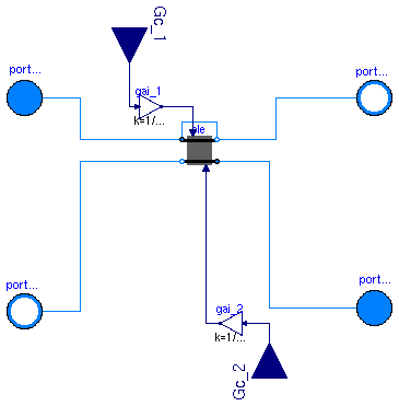
Register of a heat exchanger with dynamics on the fluids and the solid. The register represents one array of pipes that are perpendicular to the air stream. The hA value for both fluids is an input. The driving force for the heat transfer is the temperature difference between the fluid volumes and the solid in each heat exchanger element.
| Type | Name | Default | Description |
|---|---|---|---|
| Integer | nPipPar | 2 | Number of parallel pipes in each register |
| Integer | nPipSeg | 3 | Number of pipe segments per register used for discretization |
| Boolean | allowCondensation | true | Set to false to compute sensible heat transfer only |
| Fluid 1 | |||
| replaceable package Medium_1 | PartialMedium | Fluid 1 | |
| Boolean | steadyState_1 | false | Set to true for steady state model for fluid 1 |
| Fluid 2 | |||
| replaceable package Medium_2 | PartialMedium | Fluid 2 | |
| Boolean | steadyState_2 | false | Set to true for steady state model for fluid 2 |
| Nominal condition | |||
| HeatFlowRate | UA0 | Thermal conductance at nominal flow, used to compute time constant [W] | |
| MassFlowRate | m0_flow_1 | Mass flow rate medim 1 [kg/s] | |
| MassFlowRate | m0_flow_2 | Mass flow rate medium 2 [kg/s] | |
| Time | tau_1 | 20 | Time constant at nominal flow for medium 1 [s] |
| Time | tau_2 | 1 | Time constant at nominal flow for medium 2 [s] |
| Time | tau_m | 60 | Time constant of metal at nominal UA value [s] |
| Advanced | |||
| Temp | flowDirection_1 | Modelica_Fluid.Types.FlowDir... | Unidirectional (port_a -> port_b) or bidirectional flow component |
| Temp | flowDirection_2 | Modelica_Fluid.Types.FlowDir... | Unidirectional (port_a -> port_b) or bidirectional flow component |
| Type | Name | Description |
|---|---|---|
| FluidPort_a | port_a1[nPipPar] | Fluid connector a for medium 1 (positive design flow direction is from port_a1 to port_b1) |
| FluidPort_b | port_b1[nPipPar] | Fluid connector b for medium 1 (positive design flow direction is from port_a to port_b) |
| FluidPort_a | port_a2[nPipPar, nPipSeg] | Fluid connector a for medium 2 (positive design flow direction is from port_a2 to port_b2) |
| FluidPort_b | port_b2[nPipPar, nPipSeg] | Fluid connector b for medium 2 (positive design flow direction is from port_a to port_b) |
| input RealInput | Gc_2 | Signal representing the convective thermal conductance medium 2 in [W/K] |
| input RealInput | Gc_1 | Signal representing the convective thermal conductance medium 1 in [W/K] |
model CoilRegister "Register for a heat exchanger"
  extends Buildings.BaseClasses.BaseIcon;
  extends Buildings.Fluids.Interfaces.PartialDoubleFluidParameters;
  import Modelica.Constants;


  parameter Integer nPipPar(min=1)=2
    "Number of parallel pipes in each register";
  parameter Integer nPipSeg(min=1)=3
    "Number of pipe segments per register used for discretization";
  final parameter Integer nEle = nPipPar * nPipSeg
    "Number of heat exchanger elements";

  Buildings.HeatExchangers.BaseClasses.HexElement[
                      nPipPar, nPipSeg] ele(
    redeclare each package Medium_1 = Medium_1,
    redeclare each package Medium_2 = Medium_2,
    each flowDirection_1=flowDirection_1,
    each flowDirection_2=flowDirection_2,
    each tau_1=tau_1/nPipSeg,
    each m0_flow_1=m0_flow_1/nPipPar,
    each tau_2=tau_2,
    each m0_flow_2=m0_flow_2/nPipPar/nPipSeg,
    each tau_m=tau_m,
    each UA0=UA0/nPipPar/nPipSeg,
    each steadyState_1=steadyState_1,
    each steadyState_2=steadyState_2,
    each allowCondensation=allowCondensation) "Element of a heat exchanger";

  Modelica_Fluid.Interfaces.FluidPort_a[nPipPar] port_a1(
        redeclare each package Medium = Medium_1,
        each m_flow(start=0, min=if allowFlowReversal_1 then -Constants.inf else 0))
    "Fluid connector a for medium 1 (positive design flow direction is from port_a1 to port_b1)";
  Modelica_Fluid.Interfaces.FluidPort_b[nPipPar] port_b1(
        redeclare each package Medium = Medium_1,
        each m_flow(start=0, max=if allowFlowReversal_1 then +Constants.inf else 0))
    "Fluid connector b for medium 1 (positive design flow direction is from port_a to port_b)";
  Modelica_Fluid.Interfaces.FluidPort_a[nPipPar,nPipSeg] port_a2(
        redeclare each package Medium = Medium_2,
        each m_flow(start=0, min=if allowFlowReversal_2 then -Constants.inf else 0))
    "Fluid connector a for medium 2 (positive design flow direction is from port_a2 to port_b2)";
  Modelica_Fluid.Interfaces.FluidPort_b[nPipPar,nPipSeg] port_b2(
        redeclare each package Medium = Medium_2,
        each m_flow(start=0, max=if allowFlowReversal_2 then +Constants.inf else 0))
    "Fluid connector b for medium 2 (positive design flow direction is from port_a to port_b)";

  parameter Modelica.SIunits.HeatFlowRate UA0
    "Thermal conductance at nominal flow, used to compute time constant";

  parameter Modelica.SIunits.MassFlowRate m0_flow_1 "Mass flow rate medim 1";
  parameter Modelica.SIunits.MassFlowRate m0_flow_2 "Mass flow rate medium 2";

  parameter Modelica.SIunits.Time tau_1=20
    "Time constant at nominal flow for medium 1";
  parameter Modelica.SIunits.Time tau_2=1
    "Time constant at nominal flow for medium 2";
  parameter Boolean steadyState_1=false
    "Set to true for steady state model for fluid 1";
  parameter Boolean steadyState_2=false
    "Set to true for steady state model for fluid 2";
  Modelica.SIunits.HeatFlowRate Q_flow_1
    "Heat transfered from solid into medium 1";
  Modelica.SIunits.HeatFlowRate Q_flow_2
    "Heat transfered from solid into medium 2";
  parameter Modelica.SIunits.Time tau_m=60
    "Time constant of metal at nominal UA value";
  parameter Boolean allowCondensation = true
    "Set to false to compute sensible heat transfer only";
  Modelica.Blocks.Interfaces.RealInput Gc_2(redeclare type SignalType =
        Modelica.SIunits.ThermalConductance)
    "Signal representing the convective thermal conductance medium 2 in [W/K]";
  Modelica.Blocks.Interfaces.RealInput Gc_1(redeclare type SignalType =
        Modelica.SIunits.ThermalConductance)
    "Signal representing the convective thermal conductance medium 1 in [W/K]";
protected
  Modelica.Blocks.Math.Gain gai_1(k=1/nEle)
    "Gain medium-side 1 to take discretization into account";
  Modelica.Blocks.Math.Gain gai_2(k=1/nEle)
    "Gain medium-side 2 to take discretization into account";
equation
  Q_flow_1 = sum(ele[i,j].Q_flow_1 for i in 1:nPipPar, j in 1:nPipSeg);
  Q_flow_2 = sum(ele[i,j].Q_flow_2 for i in 1:nPipPar, j in 1:nPipSeg);
  for i in 1:nPipPar loop
    // liquid side (pipes)
    connect(ele[i,1].port_a1,       port_a1[i]);
    connect(ele[i,nPipSeg].port_b1, port_b1[i]);
    for j in 1:nPipSeg-1 loop
      connect(ele[i,j].port_b1, ele[i,j+1].port_a1);
    end for;
    // gas side (duct)                                                                                      //water connections
    for j in 1:nPipSeg loop
      connect(ele[i,j].port_a2, port_a2[i,j]);
      connect(ele[i,j].port_b2, port_b2[i,j]);
    end for;
  end for;

  connect(Gc_1, gai_1.u);
  connect(Gc_2, gai_2.u);

  for i in 1:nPipPar loop
     for j in 1:nPipSeg loop
      connect(gai_1.y, ele[i,j].Gc_1);
      connect(gai_2.y, ele[i,j].Gc_2);
     end for;
  end for;

end CoilRegister;
 Buildings.HeatExchangers.BaseClasses.DuctManifoldFixedResistance
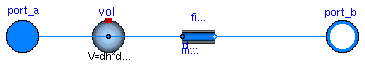
Duct manifold with a fixed flow resistance.
This model causes the flow to be distributed equally into each flow path by using a fixed flow resistance for each flow path.
| Type | Name | Default | Description |
|---|---|---|---|
| replaceable package Medium | PartialMedium | Medium in the component | |
| Integer | nPipPar | Number of parallel pipes in each register | |
| Integer | nPipSeg | Number of pipe segments per register used for discretization | |
| Boolean | use_dh | false | Set to true to specify hydraulic diameter |
| Length | dh | 1 | Hydraulic diameter of duct [m] |
| Real | ReC | 4000 | Reynolds number where transition to laminar starts |
| Real | deltaM | 0.3 | Fraction of nominal mass flow rate where transition to laminar occurs |
| Length | dl | 0.3 | Length of mixing volume [m] |
| Boolean | steadyState | false | Set to true for steady state model |
| Initialization | |||
| MassFlowRate | mStart_flow_a | Guess value for mass flow rate at port_a [kg/s] | |
| Nominal Condition | |||
| MassFlowRate | m0_flow | Mass flow rate at port_a [kg/s] | |
| Pressure | dp0 | Pressure [Pa] | |
| Advanced | |||
| Temp | flowDirection | Modelica_Fluid.Types.FlowDir... | Unidirectional (port_a -> port_b) or bidirectional flow component |
| Boolean | linearized | false | = true, use linear relation between m_flow and dp for any flow rate |
| Boolean | from_dp | false | = true, use m_flow = f(dp) else dp = f(m_flow) |
| Type | Name | Description |
|---|---|---|
| FluidPort_a | port_a | Fluid connector a for medium (positive design flow direction is from port_a to port_b) |
| FluidPort_b | port_b[nPipPar, nPipSeg] | Fluid connector b for medium (positive design flow direction is from port_a to port_b) |
model DuctManifoldFixedResistance
  "Manifold for a heat exchanger air duct connection"
  extends PartialDuctManifold;


  parameter Boolean use_dh = false "Set to true to specify hydraulic diameter";

  parameter Modelica.SIunits.MassFlowRate m0_flow "Mass flow rate at port_a";
  parameter Modelica.SIunits.Pressure dp0(min=0) "Pressure";
  parameter Modelica.SIunits.Length dh=1 "Hydraulic diameter of duct";
  parameter Real ReC=4000 "Reynolds number where transition to laminar starts";
  parameter Boolean linearized = false
    "= true, use linear relation between m_flow and dp for any flow rate";
  parameter Real deltaM(min=0) = 0.3
    "Fraction of nominal mass flow rate where transition to laminar occurs";
  parameter Boolean from_dp = false
    "= true, use m_flow = f(dp) else dp = f(m_flow)";

  Fluids.FixedResistances.FixedResistanceDpM[nPipPar,nPipSeg] fixRes(
    redeclare each package Medium = Medium,
    each m0_flow=m0_flow/nPipPar/nPipSeg,
    each m_flow(start=mStart_flow_a/nPipPar/nPipSeg),
    each dp0=dp0,
    each dh=dh/sqrt(nPipPar*nPipSeg),
    each from_dp=from_dp,
    each deltaM=deltaM,
    each ReC=ReC,
    each use_dh=use_dh,
    each linearized=linearized) "Fixed resistance for each duct";
  parameter Modelica.SIunits.Length dl = 0.3 "Length of mixing volume";
  Fluids.MixingVolumes.MixingVolume vol(redeclare package Medium =                       Medium,
    final V=dh*dh*dl,
    final nP=1+nPipPar*nPipSeg,
    final steadyState=steadyState);
  parameter Boolean steadyState=false "Set to true for steady state model";
equation
  for i in 1:nPipPar loop
    for j in 1:nPipSeg loop
   connect(vol.port[1+(i-1)*nPipSeg+j], fixRes[i, j].port_a);
    end for;
  end for;

  connect(port_a, vol.port[1]);
  connect(fixRes.port_b, port_b);
end DuctManifoldFixedResistance;
 Buildings.HeatExchangers.BaseClasses.DuctManifoldNoResistance

Duct manifold without flow resistance.
This model connects the flows between the ports without modeling flow friction. The model is used in conjunction with a manifold which contains pressure drop elements and that is added to the other side of the heat exchanger registers.
| Type | Name | Default | Description |
|---|---|---|---|
| replaceable package Medium | PartialMedium | Medium in the component | |
| Integer | nPipPar | Number of parallel pipes in each register | |
| Integer | nPipSeg | Number of pipe segments per register used for discretization | |
| Initialization | |||
| MassFlowRate | mStart_flow_a | Guess value for mass flow rate at port_a [kg/s] | |
| Advanced | |||
| Temp | flowDirection | Modelica_Fluid.Types.FlowDir... | Unidirectional (port_a -> port_b) or bidirectional flow component |
| Type | Name | Description |
|---|---|---|
| FluidPort_a | port_a | Fluid connector a for medium (positive design flow direction is from port_a to port_b) |
| FluidPort_b | port_b[nPipPar, nPipSeg] | Fluid connector b for medium (positive design flow direction is from port_a to port_b) |
model DuctManifoldNoResistance "Duct manifold without resistance"
  extends PartialDuctManifold;

equation
  for i in 1:nPipPar loop
    for j in 1:nPipSeg loop
    connect(port_a, port_b[i, j]);
    end for;
  end for;
end DuctManifoldNoResistance;
 Buildings.HeatExchangers.BaseClasses.HADryCoil
Model for sensible convective heat transfer coefficients for an air to water coil.
This model computes the convective heat transfer coefficient for an air to water coil. The parameters allow a user to enable or disable, individually for each medium, the mass flow and/or the temperature dependence of the convective heat transfer coefficients. For a detailed explanation of the equation, see the references below.
| Type | Name | Default | Description |
|---|---|---|---|
| Real | r | 0.5 | Ratio between air-side and water-side convective heat transfer coefficient |
| Real | n_w | 0.85 | Water-side exponent for convective heat transfer coefficient, h~m_flow^n |
| Real | n_a | 0.8 | Air-side exponent for convective heat transfer coefficient, h~m_flow^n |
| Nominal condition | |||
| ThermalConductance | UA0 | Thermal conductance at nominal flow [W/K] | |
| MassFlowRate | m0_flow_w | Water mass flow rate [kg/s] | |
| MassFlowRate | m0_flow_a | Air mass flow rate [kg/s] | |
| ThermalConductance | hA0_w | UA0*(r + 1)/r | Water side convective heat transfer coefficient [W/K] |
| ThermalConductance | hA0_a | r*hA0_w | Air side convective heat transfer coefficient, including fin resistance [W/K] |
| Temperature | T0_w | Modelica.SIunits.Conversions... | Water temperature [K] |
| Temperature | T0_a | Modelica.SIunits.Conversions... | Air temperature [K] |
| Advanced | |||
| Modeling detail | |||
| Boolean | waterSideFlowDependent | true | Set to false to make water-side hA independent of mass flow rate |
| Boolean | airSideFlowDependent | true | Set to false to make air-side hA independent of mass flow rate |
| Boolean | waterSideTemperatureDependent | true | Set to false to make water-side hA independent of temperature |
| Boolean | airSideTemperatureDependent | true | Set to false to make air-side hA independent of temperature |
| Type | Name | Description |
|---|---|---|
| RealSignal | m_flow_1 | Mass flow rate medium 1 |
| RealSignal | m_flow_2 | Mass flow rate medium 2 |
| RealSignal | hA_1 | Convective heat transfer medium 1 |
| RealSignal | hA_2 | Convective heat transfer medium 2 |
| RealSignal | T_1 | Temperature medium 1 |
| RealSignal | T_2 | Temperature medium 2 |
model HADryCoil
  "Sensible convective heat transfer model for air to water coil"
  extends Buildings.BaseClasses.BaseIcon;
  parameter Modelica.SIunits.ThermalConductance UA0(min=0)
    "Thermal conductance at nominal flow";

  parameter Modelica.SIunits.MassFlowRate m0_flow_w "Water mass flow rate";
  parameter Modelica.SIunits.MassFlowRate m0_flow_a "Air mass flow rate";

  Modelica.Blocks.Interfaces.RealSignal m_flow_1(redeclare type SignalType =
        Modelica.SIunits.MassFlowRate) "Mass flow rate medium 1";
  Modelica.Blocks.Interfaces.RealSignal m_flow_2(redeclare type SignalType =
        Modelica.SIunits.MassFlowRate) "Mass flow rate medium 2";
  Modelica.Blocks.Interfaces.RealSignal hA_1(redeclare type SignalType =
        Modelica.SIunits.ThermalConductance)
    "Convective heat transfer medium 1";
  Modelica.Blocks.Interfaces.RealSignal hA_2(redeclare type SignalType =
        Modelica.SIunits.ThermalConductance)
    "Convective heat transfer medium 2";
  Modelica.Blocks.Interfaces.RealSignal T_1(redeclare type SignalType =
        Modelica.SIunits.Temperature) "Temperature medium 1";
  Modelica.Blocks.Interfaces.RealSignal T_2(redeclare type SignalType =
        Modelica.SIunits.Temperature) "Temperature medium 2";

  parameter Real r(min=0, max=1)=0.5
    "Ratio between air-side and water-side convective heat transfer coefficient";
  parameter Modelica.SIunits.ThermalConductance hA0_w(min=0)=UA0 * (r+1)/r
    "Water side convective heat transfer coefficient";
  parameter Modelica.SIunits.ThermalConductance hA0_a(min=0)=r * hA0_w
    "Air side convective heat transfer coefficient, including fin resistance";
  parameter Real n_w(min=0, max=1)=0.85
    "Water-side exponent for convective heat transfer coefficient, h~m_flow^n";
  parameter Real n_a(min=0, max=1)=0.8
    "Air-side exponent for convective heat transfer coefficient, h~m_flow^n";
  parameter Modelica.SIunits.Temperature T0_w=
          Modelica.SIunits.Conversions.from_degC(20) "Water temperature";
  parameter Modelica.SIunits.Temperature T0_a=
          Modelica.SIunits.Conversions.from_degC(20) "Air temperature";
  parameter Boolean waterSideFlowDependent = true
    "Set to false to make water-side hA independent of mass flow rate";
  parameter Boolean airSideFlowDependent = true
    "Set to false to make air-side hA independent of mass flow rate";
  parameter Boolean waterSideTemperatureDependent = true
    "Set to false to make water-side hA independent of temperature";
  parameter Boolean airSideTemperatureDependent = true
    "Set to false to make air-side hA independent of temperature";
protected
  Real x_a(min=0)
    "Factor for air side temperature dependent variation of heat transfer coefficient";
  Real x_w(min=0)
    "Factor for water side temperature dependent variation of heat transfer coefficient";
  Real s_w(min=0, nominal=0.01)
    "Coefficient for temperature dependence of water side heat transfer coefficient";
  Real fm_w "Fraction of actual to nominal mass flow rate";
  Real fm_a "Fraction of actual to nominal mass flow rate";
equation
  fm_w = if waterSideFlowDependent then
              m_flow_1 / m0_flow_w else 1;
  fm_a = if airSideFlowDependent then
              m_flow_2 / m0_flow_a else 1;
  s_w =  if waterSideTemperatureDependent then
            0.014/(1+0.014*Modelica.SIunits.Conversions.to_degC(T_1)) else
              1;
  x_w = if waterSideTemperatureDependent then
         1 + s_w * (T_1-T0_w) else
              1;
  x_a = if airSideTemperatureDependent then
         1 + 4.769E-3 * (T_2-T0_a) else
              1;
  if ( waterSideFlowDependent == true) then
    hA_1 = x_w * Buildings.Utilities.Math.regNonZeroPower(fm_w, n_w, 0.1) * hA0_w;
  else
    hA_1 = x_w * hA0_w;
  end if;

  if ( airSideFlowDependent == true) then
    hA_2 = x_a * Buildings.Utilities.Math.regNonZeroPower(fm_a, n_a, 0.1) * hA0_a;
  else
    hA_2 = x_a * hA0_a;
  end if;
end HADryCoil;
 Buildings.HeatExchangers.BaseClasses.HexElement
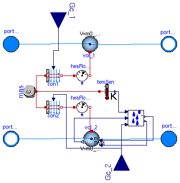
Element of a heat exchanger with dynamics on the fluids and the solid. The hA value for both fluids is an input. The driving force for the heat transfer is the temperature difference between the fluid volumes and the solid.
The heat capacity C of the metal is assigned as follows. Suppose the metal temperature is governed by
     dT
  C ---- = hA_1 (T_1 - T) + hA_2 (T_2 - T)
     dt
where hA are the convective heat transfer coefficients that also take
into account heat conduction in the heat exchanger fins and
T_1 and T_2 are the medium temperatures.
Assuming hA_1=hA_2, this equation can be rewritten as
  C       dT
 ------  ---- = (T_1 - T) + (T_2 - T)
 2 UA0    dt
where UA0 is the UA value at nominal condition. Hence we set the heat capacity of the metal to C = 2 * UA0 * tau_m.
| Type | Name | Default | Description |
|---|---|---|---|
| Boolean | allowCondensation | true | Set to false to compute sensible heat transfer only |
| Fluid 1 | |||
| replaceable package Medium_1 | PartialMedium | Fluid 1 | |
| Boolean | steadyState_1 | false | Set to true for steady state model for fluid 1 |
| Fluid 2 | |||
| replaceable package Medium_2 | PartialMedium | Fluid 2 | |
| Boolean | steadyState_2 | false | Set to true for steady state model for fluid 2 |
| Initialization | |||
| MassFlowRate | m_flow_1 | Mass flow rate from port_a1 to port_b1 (m_flow_1 > 0 is design flow direction) [kg/s] | |
| MassFlowRate | m_flow_2 | Mass flow rate from port_a2 to port_b2 (m_flow_2 > 0 is design flow direction) [kg/s] | |
| Pressure | dp_1 | Pressure difference between port_a1 and port_b1 [Pa] | |
| Pressure | dp_2 | Pressure difference between port_a2 and port_b2 [Pa] | |
| Nominal condition | |||
| Time | tau_1 | 60 | Time constant at nominal flow [s] |
| MassFlowRate | m0_flow_1 | Mass flow rate [kg/s] | |
| Time | tau_2 | 60 | Time constant at nominal flow [s] |
| MassFlowRate | m0_flow_2 | Mass flow rate [kg/s] | |
| HeatFlowRate | UA0 | Thermal conductance at nominal flow, used to compute time constant [W] | |
| Time | tau_m | 60 | Time constant of metal at nominal UA value [s] |
| Advanced | |||
| Temp | flowDirection_1 | Modelica_Fluid.Types.FlowDir... | Unidirectional (port_a -> port_b) or bidirectional flow component |
| Temp | flowDirection_2 | Modelica_Fluid.Types.FlowDir... | Unidirectional (port_a -> port_b) or bidirectional flow component |
| Type | Name | Description |
|---|---|---|
| FluidPort_a | port_a1 | Fluid connector a for medium 1 (positive design flow direction is from port_a1 to port_b1) |
| FluidPort_b | port_b1 | Fluid connector b for medium 1 (positive design flow direction is from port_a to port_b) |
| FluidPort_a | port_a2 | Fluid connector a for medium 2 (positive design flow direction is from port_a2 to port_b2) |
| FluidPort_b | port_b2 | Fluid connector b for medium 2 (positive design flow direction is from port_a to port_b) |
| input RealInput | Gc_1 | Signal representing the convective thermal conductance medium 1 in [W/K] |
| input RealInput | Gc_2 | Signal representing the convective thermal conductance medium 2 in [W/K] |
model HexElement "Element of a heat exchanger"
  extends Buildings.Fluids.Interfaces.PartialDynamicFourPortTransformer(
    final C=2*UA0*tau_m,
    mas(steadyStateStart=true),
    vol_1(redeclare package Medium = Medium_1,
          steadyState=steadyState_1,
          nP = 2,
          V=m0_flow_1*tau_1/rho0_1),
    vol_2(redeclare package Medium = Medium_2,
          steadyState=steadyState_2,
          nP = 2,
          V=m0_flow_2*tau_2/rho0_2),
    con1(dT(min=-200)),
    con2(dT(min=-200)));
  extends Buildings.BaseClasses.BaseIcon;
  // Note that we MUST declare the value of vol_2.V here.
  // Otherwise, if the class of vol_2 is redeclared at a higher level,
  // it will overwrite the assignment of V in the base class
  // PartialDynamicFourPortTransformer, which will cause V=0.
  // Assigning the values for vol_1 here is optional, but we added
  // it to be consistent in the implementation of vol_1 and vol_2.

  parameter Modelica.SIunits.HeatFlowRate UA0
    "Thermal conductance at nominal flow, used to compute time constant";
  parameter Modelica.SIunits.Time tau_m(min=0) = 60
    "Time constant of metal at nominal UA value";
  Modelica.Blocks.Interfaces.RealInput Gc_1(redeclare type SignalType =
        Modelica.SIunits.ThermalConductance)
    "Signal representing the convective thermal conductance medium 1 in [W/K]";
  Modelica.Blocks.Interfaces.RealInput Gc_2(redeclare type SignalType =
        Modelica.SIunits.ThermalConductance)
    "Signal representing the convective thermal conductance medium 2 in [W/K]";
  parameter Boolean steadyState_1=false
    "Set to true for steady state model for fluid 1";
  parameter Boolean steadyState_2=false
    "Set to true for steady state model for fluid 2";

  parameter Boolean allowCondensation = true
    "Set to false to compute sensible heat transfer only";

  MassExchange masExc(
       redeclare package Medium = Medium_2) if allowCondensation
    "Model for mass exchange";
equation
  connect(Gc_1, con1.Gc);
  connect(Gc_2, con2.Gc);
  connect(temSen.T, masExc.TSur);
  connect(Gc_2, masExc.Gc);
  connect(masExc.mWat_flow, vol_2.mWat_flow);
  connect(masExc.TLiq, vol_2.TWat);
  connect(vol_2.XWat, masExc.XInf);
end HexElement;
 Buildings.HeatExchangers.BaseClasses.MassExchange
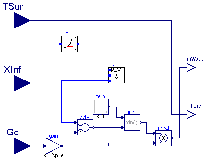
This model computes the mass transfer based on similarity laws between the convective sensible heat transfer coefficient and the mass transfer coefficient.
Using the Lewis number which is defined as the ratio between the heat and mass diffusion coefficients, one can obtain the ratio between convection heat transfer coefficient h (in W/(m^2*K)) and mass transfer coefficient h_m (in m/s) as follows:
  h
 --- = rho * c_p * Le^(1-n),
 h_m
where rho is the mass density, c_p is the specific heat capacity of the bulk medium and n is a coefficient from the boundary layer analysis, which is typically n=1/3. From this equation, we can compute the water vapor mass flow rate n_A in (kg/s) as
n_A = (Gc) / c_p / Le^(1-n) * (X_s - X_inf),where Gc is the sensible heat conductivity in (W/K) and X_s and X_inf are the water vapor mass per unit volume in the boundary layer and in the bulk of the medium. In this model, X_s is the saturation water vapor pressure corresponding to the temperature T_sur which is an input.
| Type | Name | Default | Description |
|---|---|---|---|
| Real | Le | 1 | Lewis number (around 1 for water vapor in air) |
| Real | n | 1/3 | Exponent in bondary layer ratio, delta/delta_t = Pr^n |
| Type | Name | Description |
|---|---|---|
| input RealInput | XInf | Water mass fraction of medium |
| input RealInput | TSur | Surface temperature |
| output RealOutput | mWat_flow | Water flow rate |
| output RealOutput | TLiq | Temperature at which condensate drains from system |
| input RealInput | Gc | Signal representing the convective (sensible) thermal conductance in [W/K] |
model MassExchange
  "Block to compute the latent heat transfer based on the Lewis number"
  extends Buildings.BaseClasses.BaseIcon;
  replaceable package Medium = Modelica.Media.Interfaces.PartialMedium
    "Fluid medium model";

  Modelica.Blocks.Interfaces.RealInput XInf(redeclare type SignalType =
        Modelica.SIunits.MassFraction) "Water mass fraction of medium";
  Modelica.Blocks.Interfaces.RealInput TSur(redeclare type SignalType =
        Modelica.SIunits.Temperature) "Surface temperature";
  Modelica.Blocks.Interfaces.RealOutput mWat_flow(redeclare type SignalType =
        Modelica.SIunits.MassFlowRate) "Water flow rate";
  Modelica.Blocks.Interfaces.RealOutput TLiq(redeclare type SignalType =
        Modelica.SIunits.Temperature)
    "Temperature at which condensate drains from system";
  Modelica.Blocks.Interfaces.RealInput Gc(redeclare type SignalType =
        Modelica.SIunits.ThermalConductance)
    "Signal representing the convective (sensible) thermal conductance in [W/K]";
  parameter Real Le = 1 "Lewis number (around 1 for water vapor in air)";
  parameter Real n = 1/3
    "Exponent in bondary layer ratio, delta/delta_t = Pr^n";
public
  Utilities.Psychrometrics.HumidityRatioPressure humRatPre
    "Model to convert water vapor pressure into humidity ratio";
  Utilities.Psychrometrics.DewPointTemperature TDewPoi
    "Model to compute the water vapor pressure at the dew point";
  Modelica.Blocks.Math.Gain gain(k=1/cpLe)
    "Constant to convert from heat transfer to mass transfer";
  Modelica.Blocks.Math.Product mWat "Water flow rate";
  Modelica.Blocks.Math.Min min;
  Modelica.Blocks.Sources.Constant zero(k=0) "Constant for zero";
  Modelica.Blocks.Math.Add delX(k2=-1, k1=1) "Humidity difference";
protected
 parameter Medium.ThermodynamicState sta0(T=Medium.T_default,
       p=Medium.p_default);
 parameter Modelica.SIunits.SpecificHeatCapacity cp=Medium.specificHeatCapacityCp(sta0)
    "Density, used to compute fluid volume";
 parameter Real cpLe(unit="J/kg/K") = cp * Le^(1-n);
equation
  connect(TSur, TDewPoi.T);
  connect(TDewPoi.p_w, humRatPre.p_w);
  connect(TSur, TLiq);
  connect(Gc, gain.u);
  connect(gain.y, mWat.u2);
  connect(mWat.y, mWat_flow);
  connect(zero.y,min. u1);
  connect(delX.u2,XInf);
  connect(humRatPre.XWat, delX.u1);
  connect(delX.y, min.u2);
  connect(min.y, mWat.u1);
end MassExchange;
 Buildings.HeatExchangers.BaseClasses.PartialDuctManifold

Partial duct manifold for a heat exchanger.
This model defines the duct connection to a heat exchanger. It is extended by other models that model the flow connection between the ports with and without flow friction.
| Type | Name | Default | Description |
|---|---|---|---|
| replaceable package Medium | PartialMedium | Medium in the component | |
| Integer | nPipPar | Number of parallel pipes in each register | |
| Integer | nPipSeg | Number of pipe segments per register used for discretization | |
| Initialization | |||
| MassFlowRate | mStart_flow_a | Guess value for mass flow rate at port_a [kg/s] | |
| Advanced | |||
| Temp | flowDirection | Modelica_Fluid.Types.FlowDir... | Unidirectional (port_a -> port_b) or bidirectional flow component |
| Type | Name | Description |
|---|---|---|
| FluidPort_a | port_a | Fluid connector a for medium (positive design flow direction is from port_a to port_b) |
| FluidPort_b | port_b[nPipPar, nPipSeg] | Fluid connector b for medium (positive design flow direction is from port_a to port_b) |
partial model PartialDuctManifold
  "Partial manifold for heat exchanger duct connection"
  extends PartialDuctPipeManifold;
  parameter Integer nPipSeg(min=1)
    "Number of pipe segments per register used for discretization";

  Modelica_Fluid.Interfaces.FluidPort_b[nPipPar,nPipSeg] port_b(
        redeclare each package Medium = Medium,
        each m_flow(start=-mStart_flow_a/nPipSeg/nPipPar,
             max=if allowFlowReversal then +Modelica.Constants.inf else 0))
    "Fluid connector b for medium (positive design flow direction is from port_a to port_b)";
end PartialDuctManifold;
 Buildings.HeatExchangers.BaseClasses.PartialDuctPipeManifold

Partial heat exchanger manifold. This partial model defines ports and parameters that are used for air-side and water-side heat exchanger manifolds.
| Type | Name | Default | Description |
|---|---|---|---|
| replaceable package Medium | PartialMedium | Medium in the component | |
| Integer | nPipPar | Number of parallel pipes in each register | |
| Initialization | |||
| MassFlowRate | mStart_flow_a | Guess value for mass flow rate at port_a [kg/s] | |
| Advanced | |||
| Temp | flowDirection | Modelica_Fluid.Types.FlowDir... | Unidirectional (port_a -> port_b) or bidirectional flow component |
| Type | Name | Description |
|---|---|---|
| FluidPort_a | port_a | Fluid connector a for medium (positive design flow direction is from port_a to port_b) |
partial model PartialDuctPipeManifold
  "Partial heat exchanger duct and pipe manifold"
  extends Buildings.BaseClasses.BaseIcon;
  extends Buildings.Fluids.Interfaces.PartialSingleFluidParameters;

  parameter Integer nPipPar(min=1) "Number of parallel pipes in each register";

  parameter Modelica.SIunits.MassFlowRate mStart_flow_a
    "Guess value for mass flow rate at port_a";

  Modelica_Fluid.Interfaces.FluidPort_a port_a(
        redeclare package Medium = Medium,
        m_flow(start=mStart_flow_a, min=if allowFlowReversal then -Modelica.Constants.inf else 0))
    "Fluid connector a for medium (positive design flow direction is from port_a to port_b)";
end PartialDuctPipeManifold;
 Buildings.HeatExchangers.BaseClasses.PartialPipeManifold

Partial pipe manifold for a heat exchanger.
This model defines the pipe connection to a heat exchanger. It is extended by other models that model the flow connection between the ports with and without flow friction.
| Type | Name | Default | Description |
|---|---|---|---|
| replaceable package Medium | PartialMedium | Medium in the component | |
| Integer | nPipPar | Number of parallel pipes in each register | |
| Initialization | |||
| MassFlowRate | mStart_flow_a | Guess value for mass flow rate at port_a [kg/s] | |
| Advanced | |||
| Temp | flowDirection | Modelica_Fluid.Types.FlowDir... | Unidirectional (port_a -> port_b) or bidirectional flow component |
| Type | Name | Description |
|---|---|---|
| FluidPort_a | port_a | Fluid connector a for medium (positive design flow direction is from port_a to port_b) |
| FluidPort_b | port_b[nPipPar] | Fluid connector b for medium (positive design flow direction is from port_a to port_b) |
partial model PartialPipeManifold
  "Partial pipe manifold for a heat exchanger"
  extends PartialDuctPipeManifold;
  Modelica_Fluid.Interfaces.FluidPort_b[nPipPar] port_b(
        redeclare each package Medium = Medium,
        each m_flow(start=-mStart_flow_a/nPipPar, max=if allowFlowReversal then +Modelica.Constants.inf else 0))
    "Fluid connector b for medium (positive design flow direction is from port_a to port_b)";
end PartialPipeManifold;
 Buildings.HeatExchangers.BaseClasses.PipeManifoldFixedResistance
Pipe manifold with a fixed flow resistance.
This model causes the flow to be distributed equally into each flow path by using a fixed flow resistance for each flow path.
| Type | Name | Default | Description |
|---|---|---|---|
| replaceable package Medium | PartialMedium | Medium in the component | |
| Integer | nPipPar | Number of parallel pipes in each register | |
| Boolean | use_dh | false | Set to true to specify hydraulic diameter |
| Length | dh | 0.025 | Hydraulic diameter for each pipe [m] |
| Real | ReC | 4000 | Reynolds number where transition to laminar starts |
| Real | deltaM | 0.3 | Fraction of nominal mass flow rate where transition to laminar occurs |
| Initialization | |||
| MassFlowRate | mStart_flow_a | Guess value for mass flow rate at port_a [kg/s] | |
| Nominal Condition | |||
| MassFlowRate | m0_flow | Mass flow rate at port_a [kg/s] | |
| Pressure | dp0 | Pressure [Pa] | |
| Advanced | |||
| Temp | flowDirection | Modelica_Fluid.Types.FlowDir... | Unidirectional (port_a -> port_b) or bidirectional flow component |
| Boolean | linearized | false | = true, use linear relation between m_flow and dp for any flow rate |
| Boolean | from_dp | false | = true, use m_flow = f(dp) else dp = f(m_flow) |
| Type | Name | Description |
|---|---|---|
| FluidPort_a | port_a | Fluid connector a for medium (positive design flow direction is from port_a to port_b) |
| FluidPort_b | port_b[nPipPar] | Fluid connector b for medium (positive design flow direction is from port_a to port_b) |
model PipeManifoldFixedResistance
  "Pipe manifold for a heat exchanger connection"
  extends PartialPipeManifold;

  parameter Modelica.SIunits.MassFlowRate m0_flow "Mass flow rate at port_a";
  parameter Modelica.SIunits.Pressure dp0(min=0) "Pressure";

  parameter Boolean use_dh = false "Set to true to specify hydraulic diameter";
  parameter Modelica.SIunits.Length dh=0.025 "Hydraulic diameter for each pipe";
  parameter Real ReC=4000 "Reynolds number where transition to laminar starts";
  parameter Boolean linearized = false
    "= true, use linear relation between m_flow and dp for any flow rate";
  parameter Real deltaM(min=0) = 0.3
    "Fraction of nominal mass flow rate where transition to laminar occurs";
  parameter Boolean from_dp = false
    "= true, use m_flow = f(dp) else dp = f(m_flow)";

  Fluids.FixedResistances.FixedResistanceDpM[nPipPar] fixRes(
    redeclare each package Medium = Medium,
    each m0_flow=m0_flow/nPipPar,
    each m_flow(start=mStart_flow_a),
    each dp0=dp0,
    each dh=dh,
    each from_dp=from_dp,
    each deltaM=deltaM,
    each ReC=ReC,
    each use_dh=use_dh,
    each linearized=linearized) "Fixed resistance for each duct";
equation
  for i in 1:nPipPar loop
    connect(port_a, fixRes[i].port_a);
    connect(fixRes[i].port_b, port_b[i]);
  end for;
end PipeManifoldFixedResistance;
 Buildings.HeatExchangers.BaseClasses.PipeManifoldNoResistance

Pipe manifold without flow resistance.
This model connects the flows between the ports without modeling flow friction. The model is used in conjunction with a manifold which contains pressure drop elements and that is added to the other side of the heat exchanger registers.
| Type | Name | Default | Description |
|---|---|---|---|
| replaceable package Medium | PartialMedium | Medium in the component | |
| Integer | nPipPar | Number of parallel pipes in each register | |
| Boolean | connectAllPressures | true | |
| Initialization | |||
| MassFlowRate | mStart_flow_a | Guess value for mass flow rate at port_a [kg/s] | |
| Advanced | |||
| Temp | flowDirection | Modelica_Fluid.Types.FlowDir... | Unidirectional (port_a -> port_b) or bidirectional flow component |
| Type | Name | Description |
|---|---|---|
| FluidPort_a | port_a | Fluid connector a for medium (positive design flow direction is from port_a to port_b) |
| FluidPort_b | port_b[nPipPar] | Fluid connector b for medium (positive design flow direction is from port_a to port_b) |
model PipeManifoldNoResistance "Manifold for heat exchanger register"
  extends PartialPipeManifold;
 parameter Boolean connectAllPressures=true;
equation
  for i in 1:nPipPar loop
   if (connectAllPressures == true) then
     port_a.p = port_b[i].p;
   end if;
    port_a.h = port_b[i].h;
    port_a.Xi = port_b[i].Xi;
    port_a.C = port_b[i].C;
  end for;
   if (connectAllPressures == false) then
     port_a.p = port_b[1].p;
        for i in 2:nPipPar loop
          port_b[1].m_flow = port_b[i].m_flow;
        end for;
   end if;

   port_a.m_flow + sum(port_b[i].m_flow for i in 1:nPipPar) = 0;
   port_a.H_flow + sum(port_b[i].H_flow  for i in 1:nPipPar) = 0;
   port_a.mXi_flow + sum(port_b[i].mXi_flow for i in 1:nPipPar) = zeros(Medium.nXi);
   port_a.mC_flow + sum(port_b[i].mC_flow for i in 1:nPipPar) = zeros(Medium.nC);
end PipeManifoldNoResistance;