| Name | Description |
|---|---|
| Package with base classes for heat exchanger models | |
| Heat exchanger with constant effectiveness | |
| Package with cooling tower models | |
| Heat exchanger with discretization along the flow path | |
| Simple heat exchanger with convective heat transfer as input | |
| Collection of models that illustrate model use and test models | |
| Ideal electric heater or cooler, no losses, no dynamics |
 Buildings.HeatExchangers.ConstantEffectiveness
Model for a heat exchanger with constant effectiveness.
This model transfers heat in the amount of
Q = Q_max * eps,where eps is a constant effectiveness and Q_max is the maximum heat that can be transferred.
| Type | Name | Default | Description |
|---|---|---|---|
| Real | eps | 0.8 | Heat exchanger effectiveness |
| Fluid 1 | |||
| replaceable package Medium_1 | PartialMedium | Fluid 1 | |
| Fluid 2 | |||
| replaceable package Medium_2 | PartialMedium | Fluid 2 | |
| Initialization | |||
| MassFlowRate | m_flow_1 | Mass flow rate from port_a1 to port_b1 (m_flow_1 > 0 is design flow direction) [kg/s] | |
| MassFlowRate | m_flow_2 | Mass flow rate from port_a2 to port_b2 (m_flow_2 > 0 is design flow direction) [kg/s] | |
| Pressure | dp_1 | Pressure difference between port_a1 and port_b1 [Pa] | |
| Pressure | dp_2 | Pressure difference between port_a2 and port_b2 [Pa] | |
| Advanced | |||
| Temp | flowDirection_1 | Modelica_Fluid.Types.FlowDir... | Unidirectional (port_a -> port_b) or bidirectional flow component |
| Temp | flowDirection_2 | Modelica_Fluid.Types.FlowDir... | Unidirectional (port_a -> port_b) or bidirectional flow component |
| Type | Name | Description |
|---|---|---|
| FluidPort_a | port_a1 | Fluid connector a for medium 1 (positive design flow direction is from port_a1 to port_b1) |
| FluidPort_b | port_b1 | Fluid connector b for medium 1 (positive design flow direction is from port_a to port_b) |
| FluidPort_a | port_a2 | Fluid connector a for medium 2 (positive design flow direction is from port_a2 to port_b2) |
| FluidPort_b | port_b2 | Fluid connector b for medium 2 (positive design flow direction is from port_a to port_b) |
model ConstantEffectiveness
  "Heat exchanger with constant effectiveness"
  extends Fluids.Interfaces.PartialStaticFourPortHeatMassTransfer;
  extends Buildings.BaseClasses.BaseIcon;
  parameter Real eps(min=0, max=1) = 0.8 "Heat exchanger effectiveness";

  Modelica.SIunits.Temperature T_in1 "Inlet temperature medium 1";
  Modelica.SIunits.Temperature T_in2 "Inlet temperature medium 2";
  Modelica.SIunits.ThermalConductance C_flow_1
    "Heat capacity flow rate medium 1";
  Modelica.SIunits.ThermalConductance C_flow_2
    "Heat capacity flow rate medium 2";
  Modelica.SIunits.ThermalConductance CMin_flow(min=0)
    "Minimum heat capacity flow rate";
  Modelica.SIunits.HeatFlowRate QMax_flow "Maximum heat flow rate";

equation
  // definitions for heat transfer effectiveness model
  T_in1 = if m_flow_1 >= 0 then medium_a1.T else medium_b1.T;
  T_in2 = if m_flow_2 >= 0 then medium_a2.T else medium_b2.T;
  C_flow_1 = abs(m_flow_1)
          * Medium_1.specificHeatCapacityCp(Medium_1.setState_pTX(medium_a1.p,
                medium_a1.T, medium_a1.X));
  C_flow_2 = abs(m_flow_2)
          * Medium_2.specificHeatCapacityCp(Medium_2.setState_pTX(medium_a2.p,
                medium_a2.T, medium_a2.X));

  CMin_flow = min( C_flow_1, C_flow_2);
  QMax_flow = CMin_flow * (T_in2 - T_in1);

  // transferred heat
  Q_flow_1 = eps * QMax_flow;
  0 = Q_flow_1 + Q_flow_2;

  // no mass exchange
  mXi_flow_1 = zeros(Medium_1.nXi);
  mXi_flow_2 = zeros(Medium_2.nXi);

  // no pressure drop
  dp_1 = 0;
  dp_2 = 0;
end ConstantEffectiveness;
 Buildings.HeatExchangers.DryCoilDiscretized
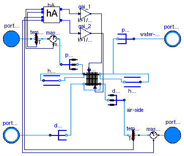
Model of a discretized coil with no water vapor condensation. The coil consists of nReg registers that are perpendicular to the air flow path. Each register consists of nPipPar parallel pipes, and each pipe can be divided into nPipSeg pipe segments along the pipe length. Thus, the smallest element of the coil consists of a pipe segment. These pipe segments are modeled by the instance ele. Each element has a state variable for the metal. Depending on the value of the boolean parameters steadyState_1 and steadyState_2, the fluid states are modeled dynamically or in steady state. If the parameter steadyStateDuctConnection is set the false then a mixing volume of length dl is added to the duct connection. This can help reducing the dimension of the nonlinear system of equations.
The convective heat transfer coefficients can, for each fluid individually, be computed as a function of the flow rate and/or the temperature, or assigned to a constant. This computation is done in the instance hA.
In this model, the water (or liquid) flow path needs to be connected to port_a1 and port_b1, and the air flow path need to be connected to the other two ports.
To model humidity condensation, use the model Buildings.HeatExchangers.WetCoilDiscretized instead of this model, as this model computes only sensible heat transfer.
| Type | Name | Default | Description |
|---|---|---|---|
| Fluid 1 | |||
| replaceable package Medium_1 | PartialMedium | Fluid 1 | |
| Boolean | steadyState_1 | false | Set to true for steady state model for fluid 1 |
| Fluid 2 | |||
| replaceable package Medium_2 | PartialMedium | Fluid 2 | |
| Boolean | steadyState_2 | true | Set to true for steady state model for fluid 2 |
| Boolean | steadyStateDuctConnection | false | Set to true for steady state model for the connection between the air duct and the heat exchanger |
| Length | dl | 0.3 | Length of mixing volume for duct connection [m] |
| Initialization | |||
| MassFlowRate | m_flow_1 | Mass flow rate from port_a1 to port_b1 (m_flow_1 > 0 is design flow direction) [kg/s] | |
| MassFlowRate | m_flow_2 | Mass flow rate from port_a2 to port_b2 (m_flow_2 > 0 is design flow direction) [kg/s] | |
| Pressure | dp_1 | Pressure difference between port_a1 and port_b1 [Pa] | |
| Pressure | dp_2 | Pressure difference between port_a2 and port_b2 [Pa] | |
| MassFlowRate | mStart_flow_a1 | m0_flow_1 | Guess value for mass flow rate at port_a1 [kg/s] |
| MassFlowRate | mStart_flow_a2 | m0_flow_2 | Guess value for mass flow rate at port_a2 [kg/s] |
| Nominal condition | |||
| Temperature | dT0 | 10 | Temperature difference [K] |
| HeatFlowRate | Q0_flow | 1000 | Heat transfer at dT0 [W] |
| ThermalConductance | UA0 | Q0_flow/dT0 | Thermal conductance at nominal flow, used to compute heat capacity [W/K] |
| MassFlowRate | m0_flow_1 | Mass flow rate at port_a1 for all pipes [kg/s] | |
| Pressure | dp0_1 | Pressure drop for all pipes [Pa] | |
| MassFlowRate | m0_flow_2 | Mass flow rate at port_a_2 for duct [kg/s] | |
| Pressure | dp0_2 | Pressure drop inside duct [Pa] | |
| Time | tau_1 | 20 | Time constant at nominal flow for medium 1 [s] |
| Time | tau_2 | 1 | Time constant at nominal flow for medium 2 [s] |
| Time | tau_m | 20 | Time constant of metal at nominal UA value [s] |
| Geometry | |||
| Integer | nReg | 2 | Number of registers |
| Integer | nPipPar | 3 | Number of parallel pipes in each register |
| Integer | nPipSeg | 4 | Number of pipe segments per register used for discretization |
| Length | dh_1 | 0.025 | Hydraulic diameter for a single pipe [m] |
| Length | dh_2 | 1 | Hydraulic diameter for duct [m] |
| Advanced | |||
| Temp | flowDirection_1 | Modelica_Fluid.Types.FlowDir... | Unidirectional (port_a -> port_b) or bidirectional flow component |
| Temp | flowDirection_2 | Modelica_Fluid.Types.FlowDir... | Unidirectional (port_a -> port_b) or bidirectional flow component |
| Boolean | from_dp_1 | false | = true, use m_flow = f(dp) else dp = f(m_flow) |
| Boolean | from_dp_2 | false | = true, use m_flow = f(dp) else dp = f(m_flow) |
| Real | deltaM_1 | 0.3 | Fraction of nominal mass flow rate where transition to laminar occurs |
| Real | deltaM_2 | 0.3 | Fraction of nominal mass flow rate where transition to laminar occurs |
| Boolean | linearized_1 | false | = true, use linear relation between m_flow and dp for any flow rate |
| Boolean | linearized_2 | false | = true, use linear relation between m_flow and dp for any flow rate |
| Boolean | use_dh_1 | false | Set to true to specify hydraulic diameter for pipe pressure drop |
| Boolean | use_dh_2 | false | Set to true to specify hydraulic diameter for duct pressure drop) |
| Real | ReC_1 | 4000 | Reynolds number where transition to laminar starts inside pipes |
| Real | ReC_2 | 4000 | Reynolds number where transition to laminar starts inside ducts |
| Heat transfer | |||
| Boolean | waterSideFlowDependent | false | Set to false to make water-side hA independent of mass flow rate |
| Boolean | airSideFlowDependent | false | Set to false to make air-side hA independent of mass flow rate |
| Boolean | waterSideTemperatureDependent | false | Set to false to make water-side hA independent of temperature |
| Type | Name | Description |
|---|---|---|
| FluidPort_a | port_a1 | Fluid connector a for medium 1 (positive design flow direction is from port_a1 to port_b1) |
| FluidPort_b | port_b1 | Fluid connector b for medium 1 (positive design flow direction is from port_a to port_b) |
| FluidPort_a | port_a2 | Fluid connector a for medium 2 (positive design flow direction is from port_a2 to port_b2) |
| FluidPort_b | port_b2 | Fluid connector b for medium 2 (positive design flow direction is from port_a to port_b) |
model DryCoilDiscretized
  "Heat exchanger with discretization along the flow path"
  extends Fluids.Interfaces.PartialStaticFourPortInterface;
  extends Buildings.BaseClasses.BaseIcon;


  parameter Modelica.SIunits.Temperature dT0(min=0) = 10
    "Temperature difference";
  parameter Modelica.SIunits.HeatFlowRate Q0_flow(min=0) = 1000
    "Heat transfer at dT0";
  parameter Modelica.SIunits.ThermalConductance UA0(min=0) = Q0_flow/dT0
    "Thermal conductance at nominal flow, used to compute heat capacity";
  parameter Integer nReg(min=2)=2 "Number of registers";
  parameter Integer nPipPar(min=1) = 3
    "Number of parallel pipes in each register";
  parameter Integer nPipSeg(min=1) = 4
    "Number of pipe segments per register used for discretization";
  parameter Boolean steadyState_1=false
    "Set to true for steady state model for fluid 1";
  parameter Boolean steadyState_2=true
    "Set to true for steady state model for fluid 2";
  parameter Boolean from_dp_1 = false
    "= true, use m_flow = f(dp) else dp = f(m_flow)";
  parameter Boolean from_dp_2 = false
    "= true, use m_flow = f(dp) else dp = f(m_flow)";
  parameter Real deltaM_1(min=0) = 0.3
    "Fraction of nominal mass flow rate where transition to laminar occurs";
  parameter Real deltaM_2(min=0) = 0.3
    "Fraction of nominal mass flow rate where transition to laminar occurs";
  parameter Boolean linearized_1 = false
    "= true, use linear relation between m_flow and dp for any flow rate";
  parameter Boolean linearized_2 = false
    "= true, use linear relation between m_flow and dp for any flow rate";
  parameter Boolean use_dh_1 = false
    "Set to true to specify hydraulic diameter for pipe pressure drop";
  parameter Boolean use_dh_2 = false
    "Set to true to specify hydraulic diameter for duct pressure drop)";

  Buildings.HeatExchangers.BaseClasses.CoilRegister hexReg[nReg](
    redeclare each package Medium_1 = Medium_1,
    redeclare each package Medium_2 = Medium_2,
    each final flowDirection_1=flowDirection_1,
    each final flowDirection_2=flowDirection_2,
    each final nPipPar=nPipPar,
    each final nPipSeg=nPipSeg,
    each final UA0=Q0_flow/dT0/nReg,
    each final m0_flow_1=m0_flow_1/nPipPar,
    each final m0_flow_2=m0_flow_1/nPipPar/nPipSeg,
    each tau_1=tau_1,
    each tau_2=tau_2,
    each tau_m=tau_m,
    each final steadyState_1=steadyState_1,
    each final steadyState_2=steadyState_2,
    each allowCondensation=allowCondensation) "Heat exchanger register";
  Buildings.HeatExchangers.BaseClasses.PipeManifoldFixedResistance pipMan_a(
    redeclare package Medium = Medium_1,
    final nPipPar=nPipPar,
    final m0_flow=m0_flow_1,
    final dp0=dp0_1,
    final dh=dh_1,
    final ReC=ReC_1,
    final mStart_flow_a=mStart_flow_a1,
    final flowDirection=flowDirection_1,
    final linearized=linearized_1,
    final use_dh=use_dh_1,
    final deltaM=deltaM_1,
    final from_dp=from_dp_1) "Pipe manifold at port a";
  Buildings.HeatExchangers.BaseClasses.PipeManifoldNoResistance pipMan_b(
    redeclare package Medium = Medium_1,
    final nPipPar=nPipPar,
    final mStart_flow_a=-mStart_flow_a1) "Pipe manifold at port b";
  Buildings.HeatExchangers.BaseClasses.DuctManifoldNoResistance ducMan_b(
    redeclare package Medium = Medium_2,
    final nPipPar=nPipPar,
    final nPipSeg=nPipSeg,
    final mStart_flow_a=-mStart_flow_a2) "Duct manifold at port b";
  Buildings.HeatExchangers.BaseClasses.DuctManifoldFixedResistance ducMan_a(
    redeclare package Medium = Medium_2,
    final nPipPar = nPipPar,
    final nPipSeg = nPipSeg,
    final m0_flow=m0_flow_2,
    final dp0=dp0_2,
    final dh=dh_2,
    final ReC=ReC_2,
    dl=dl,
    final steadyState=steadyStateDuctConnection,
    final mStart_flow_a=mStart_flow_a2,
    final linearized=linearized_2,
    final flowDirection=flowDirection_2,
    final use_dh=use_dh_2,
    final deltaM=deltaM_2,
    final from_dp=from_dp_2) "Duct manifold at port a";
public
  parameter Modelica.SIunits.Length dh_1=0.025
    "Hydraulic diameter for a single pipe";
  parameter Real ReC_1=4000
    "Reynolds number where transition to laminar starts inside pipes";
  parameter Real ReC_2=4000
    "Reynolds number where transition to laminar starts inside ducts";
  parameter Modelica.SIunits.MassFlowRate m0_flow_1
    "Mass flow rate at port_a1 for all pipes";
  parameter Modelica.SIunits.Pressure dp0_1 "Pressure drop for all pipes";
  parameter Modelica.SIunits.Length dh_2=1 "Hydraulic diameter for duct";
  parameter Modelica.SIunits.MassFlowRate m0_flow_2
    "Mass flow rate at port_a_2 for duct";
  parameter Modelica.SIunits.Pressure dp0_2 "Pressure drop inside duct";
  Modelica.SIunits.HeatFlowRate Q_flow_1
    "Heat transfered from solid into medium 1";
  Modelica.SIunits.HeatFlowRate Q_flow_2
    "Heat transfered from solid into medium 2";
  parameter Modelica.SIunits.Time tau_1=20
    "Time constant at nominal flow for medium 1";
  parameter Modelica.SIunits.Time tau_2=1
    "Time constant at nominal flow for medium 2";
  parameter Modelica.SIunits.Time tau_m=20
    "Time constant of metal at nominal UA value";

protected
  BaseClasses.CoilHeader hea1[nReg/2](
      redeclare each final package Medium = Medium_1,
      each final nPipPar = nPipPar,
      each final mStart_flow_a=mStart_flow_a1) if
      nReg > 1 "Pipe header to redirect flow into next register";
  BaseClasses.CoilHeader hea2[nReg/2-1](
      redeclare each final package Medium = Medium_1,
      each final nPipPar = nPipPar,
      each final mStart_flow_a=mStart_flow_a1) if
      nReg > 2 "Pipe header to redirect flow into next register";
  Modelica.Blocks.Math.Gain gai_1(k=1/nReg)
    "Gain medium-side 1 to take discretization into account";
  Modelica.Blocks.Math.Gain gai_2(k=1/nReg)
    "Gain medium-side 2 to take discretization into account";
public
  parameter Boolean waterSideFlowDependent = false
    "Set to false to make water-side hA independent of mass flow rate";
  parameter Boolean airSideFlowDependent = false
    "Set to false to make air-side hA independent of mass flow rate";
  parameter Boolean waterSideTemperatureDependent = false
    "Set to false to make water-side hA independent of temperature";
  constant Boolean airSideTemperatureDependent = false
    "Set to false to make air-side hA independent of temperature";
  BaseClasses.HADryCoil hA(
    final UA0=UA0,
    final m0_flow_a=m0_flow_2,
    final m0_flow_w=m0_flow_1,
    final waterSideTemperatureDependent=waterSideTemperatureDependent,
    final waterSideFlowDependent=waterSideFlowDependent,
    final airSideTemperatureDependent=airSideTemperatureDependent,
    final airSideFlowDependent=airSideFlowDependent)
    "Model for convective heat transfer coefficient";
protected
  constant Boolean allowCondensation = false
    "Set to false to compute sensible heat transfer only";

protected
  Modelica_Fluid.Sensors.Temperature temSen_1(redeclare package Medium =
        Medium_1) "Temperature sensor";
  Modelica_Fluid.Sensors.MassFlowRate masFloSen_1(redeclare package Medium =
        Medium_1) "Mass flow rate sensor";
  Modelica_Fluid.Sensors.Temperature temSen_2(redeclare package Medium =
        Medium_2) "Temperature sensor";
  Modelica_Fluid.Sensors.MassFlowRate masFloSen_2(redeclare package Medium =
        Medium_2) "Mass flow rate sensor";
public
  parameter Boolean steadyStateDuctConnection=false
    "Set to true for steady state model for the connection between the air duct and the heat exchanger";
  parameter Modelica.SIunits.Length dl=0.3
    "Length of mixing volume for duct connection";
  parameter Modelica.SIunits.MassFlowRate mStart_flow_a1=m0_flow_1
    "Guess value for mass flow rate at port_a1";
  parameter Modelica.SIunits.MassFlowRate mStart_flow_a2=m0_flow_2
    "Guess value for mass flow rate at port_a2";
equation
  Q_flow_1 = sum(hexReg[i].Q_flow_1 for i in 1:nReg);
  Q_flow_2 = sum(hexReg[i].Q_flow_2 for i in 1:nReg);

  // air stream connections
  for i in 2:nReg loop
    connect(hexReg[i].port_a2, hexReg[i-1].port_b2);
  end for;
  connect(ducMan_a.port_b, hexReg[1].port_a2);
  connect(hexReg[nReg].port_b2, ducMan_b.port_b);
  connect(pipMan_a.port_b, hexReg[1].port_a1);
  connect(hexReg[nReg].port_b1, pipMan_b.port_b);
  connect(pipMan_b.port_a, port_b1);
  connect(ducMan_b.port_a, port_b2);
  for i in 1:2:nReg loop

  // header after first hex register
    connect(hexReg[i].port_b1, hea1[(i+1)/2].port_a);
    connect(hea1[(i+1)/2].port_b, hexReg[i+1].port_b1);
  end for;
  // header after 2nd hex register
  for i in 2:2:(nReg-1) loop
    connect(hexReg[i].port_a1, hea2[i/2].port_a);
    connect(hea2[i/2].port_b, hexReg[i+1].port_a1);
  end for;
  connect(port_a1, temSen_1.port_a);
  connect(temSen_1.port_b, masFloSen_1.port_a);
  connect(masFloSen_1.port_b, pipMan_a.port_a);
  connect(temSen_1.T, hA.T_1);
  connect(masFloSen_1.m_flow, hA.m_flow_1);
  connect(port_a2, masFloSen_2.port_a);
  connect(masFloSen_2.port_b, temSen_2.port_a);
  connect(temSen_2.port_b, ducMan_a.port_a);
  connect(temSen_2.T, hA.T_2);
  connect(masFloSen_2.m_flow, hA.m_flow_2);
  connect(hA.hA_1, gai_1.u);
  connect(hA.hA_2, gai_2.u);
  for i in 1:nReg loop
    connect(gai_1.y, hexReg[i].Gc_1);
    connect(gai_2.y, hexReg[i].Gc_2);
  end for;
end DryCoilDiscretized;
 Buildings.HeatExchangers.DryHexHAInput
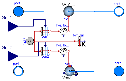
Simple heat exchanger with convective heat transfer as input. The hA values are an input and energy storage in the metal and in the fluid is taken into account.
| Type | Name | Default | Description |
|---|---|---|---|
| MixingVolumeDryAir | vol_2 | redeclare Buildings.Fluids.M... | Volume for fluid 2 |
| Fluid 1 | |||
| replaceable package Medium_1 | PartialMedium | Fluid 1 | |
| Fluid 2 | |||
| replaceable package Medium_2 | PartialMedium | Fluid 2 | |
| Initialization | |||
| MassFlowRate | m_flow_1 | Mass flow rate from port_a1 to port_b1 (m_flow_1 > 0 is design flow direction) [kg/s] | |
| MassFlowRate | m_flow_2 | Mass flow rate from port_a2 to port_b2 (m_flow_2 > 0 is design flow direction) [kg/s] | |
| Pressure | dp_1 | Pressure difference between port_a1 and port_b1 [Pa] | |
| Pressure | dp_2 | Pressure difference between port_a2 and port_b2 [Pa] | |
| Nominal condition | |||
| Time | tau_1 | 60 | Time constant at nominal flow [s] |
| MassFlowRate | m0_flow_1 | Mass flow rate [kg/s] | |
| Time | tau_2 | 60 | Time constant at nominal flow [s] |
| MassFlowRate | m0_flow_2 | Mass flow rate [kg/s] | |
| ThermalConductance | UA0 | Thermal conductance at nominal flow [W/K] | |
| Time | tau_m | 2 | Time constant of metal [s] |
| Advanced | |||
| Temp | flowDirection_1 | Modelica_Fluid.Types.FlowDir... | Unidirectional (port_a -> port_b) or bidirectional flow component |
| Temp | flowDirection_2 | Modelica_Fluid.Types.FlowDir... | Unidirectional (port_a -> port_b) or bidirectional flow component |
| Type | Name | Description |
|---|---|---|
| FluidPort_a | port_a1 | Fluid connector a for medium 1 (positive design flow direction is from port_a1 to port_b1) |
| FluidPort_b | port_b1 | Fluid connector b for medium 1 (positive design flow direction is from port_a to port_b) |
| FluidPort_a | port_a2 | Fluid connector a for medium 2 (positive design flow direction is from port_a2 to port_b2) |
| FluidPort_b | port_b2 | Fluid connector b for medium 2 (positive design flow direction is from port_a to port_b) |
| input RealInput | Gc_1 | Signal representing the convective thermal conductance of fluid 1 in [W/K] |
| input RealInput | Gc_2 | Signal representing the convective thermal conductance of fluid 2 in [W/K] |
model DryHexHAInput
  "Simple heat exchanger with convective heat transfer as input"
  extends Fluids.Interfaces.PartialDynamicFourPortTransformer(final C=tau_m*UA0);
  extends Buildings.BaseClasses.BaseIcon;


   parameter Modelica.SIunits.ThermalConductance UA0(min=0)
    "Thermal conductance at nominal flow";
  parameter Modelica.SIunits.Time tau_m(min=0) = 2 "Time constant of metal";
  Modelica.Blocks.Interfaces.RealInput Gc_1(redeclare type SignalType =
        Modelica.SIunits.ThermalConductance)
    "Signal representing the convective thermal conductance of fluid 1 in [W/K]";
  Modelica.Blocks.Interfaces.RealInput Gc_2(redeclare type SignalType =
        Modelica.SIunits.ThermalConductance)
    "Signal representing the convective thermal conductance of fluid 2 in [W/K]";
equation
  connect(Gc_1, con1.Gc);
  connect(Gc_2, con2.Gc);
end DryHexHAInput;
 Buildings.HeatExchangers.HeaterCoolerIdeal
Model for an ideal heater or cooler.
This model adds heat in the amount of Q_flow = u Q0_flow to the medium. The input signal u and the nominal heat flow rate Q0_flow can be positive or negative.
Note that if the mass flow rate tends to zero, the temperature difference over this component tends to infinity for non-zero Q_flow, so add proper control when using this component.
| Type | Name | Default | Description |
|---|---|---|---|
| replaceable package Medium | PartialMedium | Medium in the component | |
| HeatFlowRate | Q0_flow | Heat flow rate at u=1, positive for heating [W] | |
| Initialization | |||
| MassFlowRate | m_flow | Mass flow rate from port_a to port_b (m_flow > 0 is design flow direction) [kg/s] | |
| Pressure | dp | Pressure difference between port_a and port_b [Pa] | |
| Advanced | |||
| Temp | flowDirection | Modelica_Fluid.Types.FlowDir... | Unidirectional (port_a -> port_b) or bidirectional flow component |
| Type | Name | Description |
|---|---|---|
| FluidPort_a | port_a | Fluid connector a (positive design flow direction is from port_a to port_b) |
| FluidPort_b | port_b | Fluid connector b (positive design flow direction is from port_a to port_b) |
| input RealInput | u |
model HeaterCoolerIdeal
  "Ideal electric heater or cooler, no losses, no dynamics"
  extends Fluids.Interfaces.PartialStaticTwoPortHeatMassTransfer;
  extends Buildings.BaseClasses.BaseIcon;

  parameter Modelica.SIunits.HeatFlowRate Q0_flow
    "Heat flow rate at u=1, positive for heating";
  Modelica.Blocks.Interfaces.RealInput u;
equation
  dp = 0;
  Q_flow = Q0_flow * u;
  mXi_flow = zeros(Medium.nXi); // no mass added or removed (sensible heat only)
end HeaterCoolerIdeal;