This package contains functions that are used to define parameterized surfaces for use with the Surface model.
Extends from Modelica.Icons.Package (Icon for standard packages).
| Name | Description |
|---|---|
| Function defining the surface characteristic of a torus | |
| Function defining the surface characteristic of a pipe where a scalar field value is displayed with color along the pipe axis |
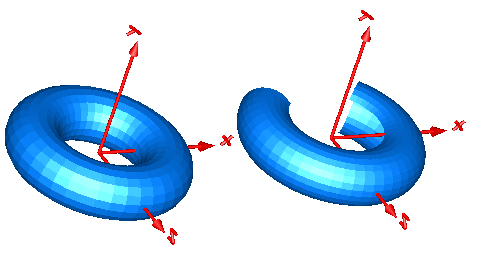
Function torus computes the X,Y,Z arrays to visualize a torus with model Torus. The left image below shows a torus with ri=0.5 m and ro = 0.2 m. The right images below shows the torus with the additional parameter settings:
  opening    =   45 degree
  startAngle = -135 degree
  stopAngle  =  135 degree
Extends from Modelica.Mechanics.MultiBody.Interfaces.partialSurfaceCharacteristic.
| Type | Name | Default | Description |
|---|---|---|---|
| Integer | nu | Number of points in u-Dimension | |
| Integer | nv | Number of points in v-Dimension | |
| Boolean | multiColoredSurface | false | = true: Color is defined for each surface point |
| Radius | ri | 1 | Inner radius of torus [m] |
| Radius | ro | 0.2 | Outer radius of torus (=width/2) [m] |
| Angle | opening | 0 | Opening angle of torus [rad] |
| Angle | startAngle | -Modelica.Constants.pi | Start angle of torus slice [rad] |
| Angle | stopAngle | Modelica.Constants.pi | End angle of torus slice [rad] |
| Type | Name | Description |
|---|---|---|
| Position | X[nu, nv] | [nu,nv] positions of points in x-Direction resolved in surface frame [m] |
| Position | Y[nu, nv] | [nu,nv] positions of points in y-Direction resolved in surface frame [m] |
| Position | Z[nu, nv] | [nu,nv] positions of points in z-Direction resolved in surface frame [m] |
| Real | C[if multiColoredSurface then nu else 0, if multiColoredSurface then nv else 0, 3] | [nu,nv,3] Color array, defining the color for each surface point |
function torus
  "Function defining the surface characteristic of a torus"
  extends Modelica.Mechanics.MultiBody.Interfaces.partialSurfaceCharacteristic(
            final multiColoredSurface=false);
  input Modelica.SIunits.Radius ri=1 "Inner radius of torus";
  input Modelica.SIunits.Radius ro=0.2 "Outer radius of torus (=width/2)";
  input Modelica.SIunits.Angle opening=0 "Opening angle of torus";
  input Modelica.SIunits.Angle startAngle= -Modelica.Constants.pi
    "Start angle of torus slice";
  input Modelica.SIunits.Angle stopAngle= Modelica.Constants.pi
    "End angle of torus slice";
protected
  Modelica.SIunits.Angle alpha;
  Modelica.SIunits.Angle beta;
  Modelica.SIunits.Angle phi_start;
  Modelica.SIunits.Angle phi_stop;
algorithm
  phi_start :=-Modelica.Constants.pi + opening;
  phi_stop  :=Modelica.Constants.pi - opening;
  for i in 1:nu loop
      alpha := startAngle + (stopAngle-startAngle)*(i-1)/(nu-1);
      for j in 1:nv loop
          beta := phi_start + (phi_stop-phi_start)*(j-1)/(nv-1);
          X[i,j] := (ri + ro*cos(beta))*sin(alpha);
          Y[i,j] := ro*sin(beta);
          Z[i,j] := (ri + ro*cos(beta))*cos(alpha);
      end for;
  end for;
end torus;
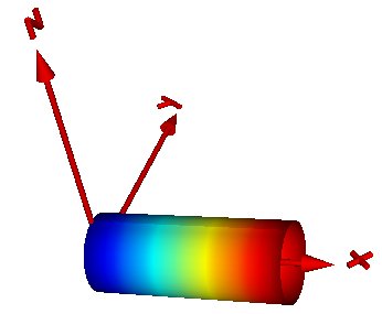
Function pipeWithScalarField computes the X,Y,Z,C arrays in order to visualize a pipe and a scalar field along the pipe axis with model PipeWithScalarField. The latter is shown by mapping scalar field to color values with a color map and utilizing this color at the perimeter associated with the corresponding axis location. Typically the scalar field value is a temperature, but might be also another quantity. Predefined color maps are available from MultiBody.Visualizers.Colors.ColorMaps and can be selected via input argument "colorMap". A color map with the corresponding scalar field values can be exported as vector-graphics in svg-format with function MultiBody.Visualizers.Colors.colorMapToSvg. An example is shown in the next figure:
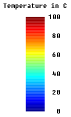
The color coding is shown in the next figure. It was generated with Mechanics.MultiBody.Visualizers.Colors.colorMapToSvg using the following call:
colorMapToSvg(Modelica.Mechanics.MultiBody.Visualizer.Colors.ColorMap.jet(),
              height=50, nScalars=6, T_max=100, heading="Temperature in C");
Extends from Modelica.Mechanics.MultiBody.Interfaces.partialSurfaceCharacteristic.
| Type | Name | Default | Description |
|---|---|---|---|
| Integer | nu | Number of points in u-Dimension | |
| Integer | nv | Number of points in v-Dimension | |
| Boolean | multiColoredSurface | true | = true: Color is defined for each surface point |
| Radius | rOuter | Outer radius of cylinder [m] | |
| Length | length | Length of cylinder [m] | |
| Position | xsi[:] | Relative position along the pipe with x[1] = 0, x[end] = 1 [m] | |
| Real | T[size(xsi, 1)] | Scalar field value at position xsi*length | |
| Real | T_min | T <= T_min is mapped to colorMap[1,:] | |
| Real | T_max | T >= T_max is mapped to colorMap[end,:] | |
| Real | colorMap[:, 3] | Color map to map scalar T to a corresponding color |
| Type | Name | Description |
|---|---|---|
| Position | X[nu, nv] | [nu,nv] positions of points in x-Direction resolved in surface frame [m] |
| Position | Y[nu, nv] | [nu,nv] positions of points in y-Direction resolved in surface frame [m] |
| Position | Z[nu, nv] | [nu,nv] positions of points in z-Direction resolved in surface frame [m] |
| Real | C[if multiColoredSurface then nu else 0, if multiColoredSurface then nv else 0, 3] | [nu,nv,3] Color array, defining the color for each surface point |
function pipeWithScalarField
  "Function defining the surface characteristic of a pipe where a scalar field value is displayed with color along the pipe axis"
  import C = Modelica.Constants;
  extends Modelica.Mechanics.MultiBody.Interfaces.partialSurfaceCharacteristic(
            final multiColoredSurface=true);
  input Modelica.SIunits.Radius rOuter "Outer radius of cylinder";
  input Modelica.SIunits.Length length "Length of cylinder";
  input Modelica.SIunits.Position xsi[:]
    "Relative position along the pipe with x[1] = 0, x[end] = 1";
  input Real T[size(xsi,1)] "Scalar field value at position xsi*length";
  input Real T_min "T <= T_min is mapped to colorMap[1,:]";
  input Real T_max "T >= T_max is mapped to colorMap[end,:]";
  input Real colorMap[:,3] "Color map to map scalar T to a corresponding color";
protected
  Real beta;
  Real xsi_i;
  Real Ti;
  Real Ci[3];
  Integer k;
algorithm
  k:=1;
  for i in 1:nu loop
     // Compute actual xsi-position along cylinder axis
     xsi_i := (i-1)/(nu-1);

     // Interpolate in xsi and T to determine the corresponding value of Ti(xsi_i)
     (Ti,k) := Modelica.Math.Vectors.interpolate(xsi, T, xsi_i, k);

     // Map the scalar field value Ti to a color value
     Ci := Modelica.Mechanics.MultiBody.Visualizers.Colors.scalarToColor(
                                              Ti, T_min, T_max, colorMap);

     // Determine outputs
     for j in 1:nv loop
        beta := 2*Modelica.Constants.pi*(j-1)/(nv-1);
        X[i,j] := length*xsi_i;
        Y[i,j] := rOuter*sin(beta);
        Z[i,j] := rOuter*cos(beta);
        C[i,j,:] := Ci;
     end for;
  end for;
end pipeWithScalarField;