The models in this package should not be used by the user. They are designed to build up other models in the MultiBody library and some of them cannot be used in an arbitrary way and require particular knowledge how to set the options in the parameter menu. Don't use the models of this package.
Extends from Modelica.Icons.Package (Icon for standard packages).
| Name | Description |
|---|---|
| Revolute joint where the rotation angle is computed from a length constraint (1 degree-of-freedom, no potential state) | |
| Prismatic joint where the translational distance is computed from a length constraint (1 degree-of-freedom, no potential state) | |
| Rolling constraint for wheel that is always perpendicular to x-y plane |
 Modelica.Mechanics.MultiBody.Joints.Internal.RevoluteWithLengthConstraint
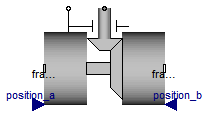
Joint where frame_b rotates around axis n which is fixed in frame_a. The two frames coincide when "phi + phi_offset = 0", where "phi_offset" is a parameter with a zero default and "phi" is the rotation angle.
This variant of the revolute joint is designed to work together with a length constraint in a kinematic loop. This means that the angle of the revolute joint, phi, is computed such that the length constraint is fulfilled.
Usually, this joint should not be used by a user of the MultiBody library. It is only provided to built-up the Modelica.Mechanics.MultiBody.Joints.Assemblies.JointXYZ joints.
In releases before version 3.0 of the Modelica Standard Library, it was possible to activate the torque projection equation (= cut-torque projected to the rotation axis must be identical to the drive torque of flange axis) via parameter axisTorqueBalance. This is no longer possible, since otherwise this model would not be "balanced" (= same number of unknowns as equations). Instead, when using this model in version 3.0 and later versions, the force in the length constraint component (Joints.SphericalSpherical or Joints.UniversalSpherical) must be calculated such that the driving torque in direction of the rotation axis is (RC shall be the name of the instance of RevoluteWithLenghtConstraint):
0 = RC.axis.tau + RC.e*RC.frame_b.t;
If this equation is used, usually the force in the length constraint and the second derivative of the revolute angle will be part of a linear algebraic system of equations. In some cases it is possible to solve this system of equations locally, i.e., provide the rod force directly as function of the revolute constraint torque. In any case, this projection equation or an equivalent one has to be provided via variable "constraintResidue" in the "Advanced" menu of "Joints.SphericalSpherical" or "Joints.UniversalSpherical".
Extends from Modelica.Mechanics.MultiBody.Interfaces.PartialTwoFrames (Base model for components providing two frame connectors + outer world + assert to guarantee that the component is connected).
| Type | Name | Default | Description |
|---|---|---|---|
| Boolean | animation | true | = true, if animation shall be enabled |
| Position | lengthConstraint | Fixed length of length constraint [m] | |
| Axis | n | {0,0,1} | Axis of rotation resolved in frame_a (= same as in frame_b) [1] |
| Angle_deg | phi_offset | 0 | Relative angle offset (angle = phi + from_deg(phi_offset)) [deg] |
| Angle_deg | phi_guess | 0 | Select the configuration such that at initial time |phi - from_deg(phi_guess)|is minimal [deg] |
| Animation | |||
| if animation = true | |||
| Distance | cylinderLength | world.defaultJointLength | Length of cylinder representing the joint axis [m] |
| Distance | cylinderDiameter | world.defaultJointWidth | Diameter of cylinder representing the joint axis [m] |
| Color | cylinderColor | Modelica.Mechanics.MultiBody... | Color of cylinder representing the joint axis |
| SpecularCoefficient | specularCoefficient | world.defaultSpecularCoeffic... | Reflection of ambient light (= 0: light is completely absorbed) |
| Type | Name | Description |
|---|---|---|
| Frame_a | frame_a | Coordinate system fixed to the component with one cut-force and cut-torque |
| Frame_b | frame_b | Coordinate system fixed to the component with one cut-force and cut-torque |
| Flange_a | axis | 1-dim. rotational flange that drives the joint |
| Flange_b | bearing | 1-dim. rotational flange of the drive bearing |
| input RealInput | position_a[3] | Position vector from frame_a to frame_a side of length constraint, resolved in frame_a of revolute joint [m] |
| input RealInput | position_b[3] | Position vector from frame_b to frame_b side of length constraint, resolved in frame_b of revolute joint [m] |
model RevoluteWithLengthConstraint "Revolute joint where the rotation angle is computed from a length constraint (1 degree-of-freedom, no potential state)" import SI = Modelica.SIunits; import Cv = Modelica.SIunits.Conversions; extends Modelica.Mechanics.MultiBody.Interfaces.PartialTwoFrames;Modelica.Mechanics.Rotational.Interfaces.Flange_a axis "1-dim. rotational flange that drives the joint"; Modelica.Mechanics.Rotational.Interfaces.Flange_b bearing "1-dim. rotational flange of the drive bearing"; Modelica.Blocks.Interfaces.RealInput position_a[3](each final quantity="Position", each final unit = "m") "Position vector from frame_a to frame_a side of length constraint, resolved in frame_a of revolute joint"; Modelica.Blocks.Interfaces.RealInput position_b[3](each final quantity="Position", each final unit="m") "Position vector from frame_b to frame_b side of length constraint, resolved in frame_b of revolute joint"; parameter Boolean animation=true "= true, if animation shall be enabled"; parameter SI.Position lengthConstraint(start=1) "Fixed length of length constraint"; parameter Modelica.Mechanics.MultiBody.Types.Axis n={0,0,1} "Axis of rotation resolved in frame_a (= same as in frame_b)"; parameter Cv.NonSIunits.Angle_deg phi_offset=0 "Relative angle offset (angle = phi + from_deg(phi_offset))"; parameter Cv.NonSIunits.Angle_deg phi_guess=0 "Select the configuration such that at initial time |phi - from_deg(phi_guess)|is minimal"; parameter SI.Distance cylinderLength=world.defaultJointLength "Length of cylinder representing the joint axis"; parameter SI.Distance cylinderDiameter=world.defaultJointWidth "Diameter of cylinder representing the joint axis"; input Types.Color cylinderColor=Modelica.Mechanics.MultiBody.Types.Defaults.JointColor "Color of cylinder representing the joint axis"; input Types.SpecularCoefficient specularCoefficient = world.defaultSpecularCoefficient "Reflection of ambient light (= 0: light is completely absorbed)"; final parameter Boolean positiveBranch(fixed=false) "Based on phi_guess, selection of one of the two solutions of the non-linear constraint equation"; final parameter Real e[3](each final unit="1")=Modelica.Math.Vectors.normalize(n,0.0) "Unit vector in direction of rotation axis, resolved in frame_a"; SI.Angle phi "Rotation angle of revolute joint"; Frames.Orientation R_rel "Relative orientation object from frame_a to frame_b"; SI.Angle angle "= phi + from_deg(phi_offset) (relative rotation angle between frame_a and frame_b)"; SI.Torque tau "= axis.tau (driving torque in the axis)"; protected SI.Position r_a[3]=position_a "Position vector from frame_a to frame_a side of length constraint, resolved in frame_a of revolute joint"; SI.Position r_b[3]=position_b "Position vector from frame_b to frame_b side of length constraint, resolved in frame_b of revolute joint"; Real e_r_a "Projection of r_a on e"; Real e_r_b "Projection of r_b on e"; Real A "Coefficient A of equation: A*cos(phi) + B*sin(phi) + C = 0"; Real B "Coefficient B of equation: A*cos(phi) + B*sin(phi) + C = 0"; Real C "Coefficient C of equation: A*cos(phi) + B*sin(phi) + C = 0"; Real k1 "Constant of quadratic equation"; Real k2 "Constant of quadratic equation"; Real k1a(start=1); Real k1b; Real kcos_angle "= k1*cos(angle)"; Real ksin_angle "= k1*sin(angle)"; Visualizers.Advanced.Shape cylinder( shapeType="cylinder", color=cylinderColor, specularCoefficient=specularCoefficient, length=cylinderLength, width=cylinderDiameter, height=cylinderDiameter, lengthDirection=e, widthDirection={0,1,0}, r_shape=-e*(cylinderLength/2), r=frame_a.r_0, R=frame_a.R) if world.enableAnimation and animation;function selectBranch "Determine branch which is closest to initial angle=0" import Modelica.Math.*; input SI.Length L "Length of length constraint"; input Real e[3](each final unit="1") "Unit vector along axis of rotation, resolved in frame_a (= same in frame_b)"; input SI.Angle angle_guess "Select the configuration such that at initial time |angle-angle_guess|is minimal (angle=0: frame_a and frame_b coincide)"; input SI.Position r_a[3] "Position vector from frame_a to frame_a side of length constraint, resolved in frame_a of revolute joint"; input SI.Position r_b[3] "Position vector from frame_b to frame_b side of length constraint, resolved in frame_b of revolute joint"; output Boolean positiveBranch "Branch of the initial solution"; protected Real e_r_a "Projection of r_a on e"; Real e_r_b "Projection of r_b on e"; Real A "Coefficient A of equation: A*cos(phi) + B*sin(phi) + C = 0"; Real B "Coefficient B of equation: A*cos(phi) + B*sin(phi) + C = 0"; Real C "Coefficient C of equation: A*cos(phi) + B*sin(phi) + C = 0"; Real k1 "Constant of quadratic equation"; Real k2 "Constant of quadratic equation"; Real k1a; Real k1b; Real kcos1 "k1*cos(angle1)"; Real ksin1 "k1*sin(angle1)"; Real kcos2 "k2*cos(angle2)"; Real ksin2 "k2*sin(angle2)"; SI.Angle angle1 "solution 1 of nonlinear equation"; SI.Angle angle2 "solution 2 of nonlinear equation"; algorithm /* The position vector r_rel from frame_a to frame_b of the length constraint element, resolved in frame_b of the revolute joint is given by (T_rel is the planar transformation matrix from frame_a to frame_b of the revolute joint): r_rel = r_b - T_rel*r_a The length constraint can therefore be formulated as: r_rel*r_rel = L*L with (r_b - T_rel*r_a)*(r_b - T_rel*r_a) = r_b*r_b - 2*r_b*T_rel*r_a + r_a*transpose(T_rel)*T_rel*r_a = r_b*r_b + r_a*r_a - 2*r_b*T_rel*r_a follows (1) 0 = r_a*r_a + r_b*r_b - 2*r_b*T_rel*r_a - L*L The vectors r_a, r_b and parameter L are NOT a function of the angle of the revolute joint. Since T_rel = T_rel(angle) is a function of the unknown angle of the revolute joint, this is a non-linear equation in this angle. T_rel = [e]*tranpose([e]) + (identity(3) - [e]*transpose([e]))*cos(angle) - skew(e)*sin(angle); with r_b*T_rel*r_a = r_b*(e*(e*r_a) + (r_a - e*(e*r_a))*cos(angle) - cross(e,r_a)*sin(angle) = (e*r_b)*(e*r_a) + (r_b*r_a - (e*r_b)*(e*r_a))*cos(angle) - r_b*cross(e,r_a)*sin(angle) follows for the constraint equation (1) (2) 0 = r_a*r_a + r_b*r_b - L*L - 2*(e*r_b)*(e*r_a) - 2*(r_b*r_a - (e*r_b)*(e*r_a))*cos(angle) + 2*r_b*cross(e,r_a)*sin(angle) or (3) A*cos(angle) + B*sin(angle) + C = 0 with A = -2*(r_b*r_a - (e*r_b)*(e*r_a)) B = 2*r_b*cross(e,r_a) C = r_a*r_a + r_b*r_b - L*L - 2*(e*r_b)*(e*r_a) Equation (3) is solved by computing sin(angle) and cos(angle) independently from each other. This allows to compute angle in the range: -180 deg <= angle <= 180 deg */ e_r_a := e*r_a; e_r_b := e*r_b; A := -2*(r_b*r_a - e_r_b*e_r_a); B := 2*r_b*cross(e, r_a); C := r_a*r_a + r_b*r_b - L*L - 2*e_r_b*e_r_a; k1 := A*A + B*B; k1a :=k1 - C*C; assert(k1a > 1.e-10, " Singular position of loop (either no or two analytic solutions; the mechanism has lost one-degree-of freedom in this position). Try first to use another Modelica.Mechanics.MultiBody.Joints.Assemblies.JointXXX component. In most cases it is best that the joints outside of the JointXXX component are revolute and NOT prismatic joints. If this also lead to singular positions, it could be that this kinematic loop cannot be solved analytically. In this case you have to build up the loop with basic joints (NO aggregation JointXXX components) and rely on dynamic state selection, i.e., during simulation the states will be dynamically selected in such a way that in no position a degree of freedom is lost. "); k1b := max(k1a, 1.0e-12); k2 := sqrt(k1b); kcos1 := -A*C + B*k2; ksin1 := -B*C - A*k2; angle1 := atan2(ksin1, kcos1); kcos2 := -A*C - B*k2; ksin2 := -B*C + A*k2; angle2 := atan2(ksin2, kcos2); if abs(angle1 - angle_guess) <= abs(angle2 - angle_guess) then positiveBranch := true; else positiveBranch := false; end if; end selectBranch ; initial equation positiveBranch = selectBranch(lengthConstraint, e, Cv.from_deg(phi_offset + phi_guess), r_a, r_b); equation Connections.branch(frame_a.R, frame_b.R); axis.tau = tau; axis.phi = phi; bearing.phi = 0; angle = Cv.from_deg(phi_offset) + phi; // transform kinematic quantities from frame_a to frame_b frame_b.r_0 = frame_a.r_0; R_rel = Frames.planarRotation(e, angle, der(angle)); frame_b.R = Frames.absoluteRotation(frame_a.R, R_rel); // Force and torque balance zeros(3) = frame_a.f + Frames.resolve1(R_rel, frame_b.f); zeros(3) = frame_a.t + Frames.resolve1(R_rel, frame_b.t); // Compute rotation angle (details, see function "selectBranch") e_r_a = e*r_a; e_r_b = e*r_b; A = -2*(r_b*r_a - e_r_b*e_r_a); B = 2*r_b*cross(e, r_a); C = r_a*r_a + r_b*r_b - lengthConstraint*lengthConstraint - 2*e_r_b*e_r_a; k1 = A*A + B*B; k1a = k1 - C*C; assert(k1a > 1.e-10, " Singular position of loop (either no or two analytic solutions; the mechanism has lost one-degree-of freedom in this position). Try first to use another Modelica.Mechanics.MultiBody.Joints.Assemblies.JointXXX component. In most cases it is best that the joints outside of the JointXXX component are revolute and NOT prismatic joints. If this also lead to singular positions, it could be that this kinematic loop cannot be solved analytically. In this case you have to build up the loop with basic joints (NO aggregation JointXXX components) and rely on dynamic state selection, i.e., during simulation the states will be dynamically selected in such a way that in no position a degree of freedom is lost. "); k1b = Frames.Internal.maxWithoutEvent(k1a, 1.0e-12); k2 = sqrt(k1b); kcos_angle = -A*C + (if positiveBranch then B else -B)*k2; ksin_angle = -B*C + (if positiveBranch then -A else A)*k2; angle = Modelica.Math.atan2(ksin_angle, kcos_angle);end RevoluteWithLengthConstraint;
 Modelica.Mechanics.MultiBody.Joints.Internal.PrismaticWithLengthConstraint
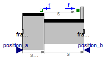
Joint where frame_b is translated along axis n which is fixed in frame_a. The two frames coincide when "s + s_offset = 0", where "s_offset" is a parameter with a zero default and "s" is the relative distance.
This variant of the prismatic joint is designed to work together with a length constraint in a kinematic loop. This means that the relative distance "s" of the joint is computed such that the length constraint is fulfilled.
Usually, this joint should not be used by a user of the MultiBody library. It is only provided to built-up the Modelica.Mechanics.MultiBody.Joints.Assemblies.JointXYZ joints.
In releases before version 3.0 of the Modelica Standard Library, it was possible to activate the force projection equation (= cut-force projected to the translation axis must be identical to the driving force of flange axis) via parameter axisForceBalance. This is no longer possible, since otherwise this model would not be "balanced" (= same number of unknowns as equations). Instead, when using this model in version 3.0 and later versions, the force in the length constraint component (Joints.SphericalSpherical or Joints.UniversalSpherical) must be calculated such that the driving force in direction of the translation axis is (RC shall be the name of the instance of PrismaticWithLenghtConstraint):
0 = RC.axis.f + RC.e*RC.frame_b.f;
If this equation is used, usually the force in the length constraint and the second derivative of the prismatic distance will be part of a linear algebraic system of equations. In some cases it is possible to solve this system of equations locally, i.e., provide the rod force directly as function of the prismatic constraint force. In any case, this projection equation or an equivalent one has to be provided via variable "constraintResidue" in the "Advanced" menu of "Joints.SphericalSpherical" or "Joints.UniversalSpherical".
Extends from Modelica.Mechanics.MultiBody.Interfaces.PartialTwoFrames (Base model for components providing two frame connectors + outer world + assert to guarantee that the component is connected).
| Type | Name | Default | Description |
|---|---|---|---|
| Boolean | animation | true | = true, if animation shall be enabled |
| Position | length | Fixed length of length constraint [m] | |
| Axis | n | {1,0,0} | Axis of translation resolved in frame_a (= same as in frame_b) [1] |
| Position | s_offset | 0 | Relative distance offset (distance between frame_a and frame_b = s(t) + s_offset) [m] |
| Position | s_guess | 0 | Select the configuration such that at initial time |s(t0)-s_guess|is minimal [m] |
| Animation | |||
| if animation = true | |||
| Axis | boxWidthDirection | {0,1,0} | Vector in width direction of box, resolved in frame_a [1] |
| Distance | boxWidth | world.defaultJointWidth | Width of prismatic joint box [m] |
| Distance | boxHeight | boxWidth | Height of prismatic joint box [m] |
| Color | boxColor | Modelica.Mechanics.MultiBody... | Color of prismatic joint box |
| SpecularCoefficient | specularCoefficient | world.defaultSpecularCoeffic... | Reflection of ambient light (= 0: light is completely absorbed) |
| Type | Name | Description |
|---|---|---|
| Frame_a | frame_a | Coordinate system fixed to the component with one cut-force and cut-torque |
| Frame_b | frame_b | Coordinate system fixed to the component with one cut-force and cut-torque |
| Flange_a | axis | 1-dim. translational flange that drives the joint |
| Flange_b | bearing | 1-dim. translational flange of the drive bearing |
| input RealInput | position_a[3] | Position vector from frame_a to frame_a side of length constraint, resolved in frame_a of revolute joint |
| input RealInput | position_b[3] | Position vector from frame_b to frame_b side of length constraint, resolved in frame_b of revolute joint |
model PrismaticWithLengthConstraint "Prismatic joint where the translational distance is computed from a length constraint (1 degree-of-freedom, no potential state)" import SI = Modelica.SIunits; import Cv = Modelica.SIunits.Conversions; extends Modelica.Mechanics.MultiBody.Interfaces.PartialTwoFrames;Modelica.Mechanics.Translational.Interfaces.Flange_a axis "1-dim. translational flange that drives the joint"; Modelica.Mechanics.Translational.Interfaces.Flange_b bearing "1-dim. translational flange of the drive bearing"; Modelica.Blocks.Interfaces.RealInput position_a[3] "Position vector from frame_a to frame_a side of length constraint, resolved in frame_a of revolute joint"; Modelica.Blocks.Interfaces.RealInput position_b[3] "Position vector from frame_b to frame_b side of length constraint, resolved in frame_b of revolute joint"; parameter Boolean animation=true "= true, if animation shall be enabled"; parameter SI.Position length(start=1) "Fixed length of length constraint"; parameter Modelica.Mechanics.MultiBody.Types.Axis n={1,0,0} "Axis of translation resolved in frame_a (= same as in frame_b)"; parameter SI.Position s_offset=0 "Relative distance offset (distance between frame_a and frame_b = s(t) + s_offset)"; parameter SI.Position s_guess=0 "Select the configuration such that at initial time |s(t0)-s_guess|is minimal"; parameter Types.Axis boxWidthDirection={0,1,0} "Vector in width direction of box, resolved in frame_a"; parameter SI.Distance boxWidth=world.defaultJointWidth "Width of prismatic joint box"; parameter SI.Distance boxHeight=boxWidth "Height of prismatic joint box"; input Types.Color boxColor=Modelica.Mechanics.MultiBody.Types.Defaults.JointColor "Color of prismatic joint box"; input Types.SpecularCoefficient specularCoefficient = world.defaultSpecularCoefficient "Reflection of ambient light (= 0: light is completely absorbed)"; final parameter Boolean positiveBranch(fixed=false) "Selection of one of the two solutions of the non-linear constraint equation"; final parameter Real e[3](each final unit="1")=Modelica.Math.Vectors.normalize(n,0.0) "Unit vector in direction of translation axis, resolved in frame_a"; SI.Position s "Relative distance between frame_a and frame_b along axis n = s + s_offset)"; SI.Position distance "Relative distance between frame_a and frame_b along axis n"; SI.Position r_rel_a[3] "Position vector from frame_a to frame_b resolved in frame_a"; SI.Force f "= axis.f (driving force in the axis)"; protected SI.Position r_a[3]=position_a "Position vector from frame_a to frame_a side of length constraint, resolved in frame_a of revolute joint"; SI.Position r_b[3]=position_b "Position vector from frame_b to frame_b side of length constraint, resolved in frame_b of revolute joint"; Modelica.SIunits.Position rbra[3] "= rb - ra"; Real B "Coefficient B of equation: s*s + B*s + C = 0"; Real C "Coefficient C of equation: s*s + B*s + C = 0"; Real k1 "Constant of quadratic equation solution"; Real k2 "Constant of quadratic equation solution"; Real k1a(start=1); Real k1b; Visualizers.Advanced.Shape box( shapeType="box", color=boxColor, specularCoefficient=specularCoefficient, length=if noEvent(abs(s + s_offset) > 1.e-6) then s + s_offset else 1.e-6, width=boxWidth, height=boxHeight, lengthDirection=e, widthDirection=boxWidthDirection, r=frame_a.r_0, R=frame_a.R) if world.enableAnimation and animation;function selectBranch "Determine branch which is closest to initial angle=0" import Modelica.Math.*; input SI.Length L "Length of length constraint"; input Real e[3](each final unit="1") "Unit vector along axis of translation, resolved in frame_a (= same in frame_b)"; input SI.Position d_guess "Select the configuration such that at initial time |d-d_guess|is minimal (d: distance between origin of frame_a and origin of frame_b)"; input SI.Position r_a[3] "Position vector from frame_a to frame_a side of length constraint, resolved in frame_a of prismatic joint"; input SI.Position r_b[3] "Position vector from frame_b to frame_b side of length constraint, resolved in frame_b of prismatic joint"; output Boolean positiveBranch "Branch of the initial solution"; protected Modelica.SIunits.Position rbra[3] "= rb - ra"; Real B "Coefficient B of equation: d*d + B*d + C = 0"; Real C "Coefficient C of equation: d*d + B*d + C = 0"; Real k1 "Constant of quadratic equation solution"; Real k2 "Constant of quadratic equation solution"; Real k1a; Real k1b; Real d1 "solution 1 of quadratic equation"; Real d2 "solution 2 of quadratic equation"; algorithm /* The position vector r_rel from frame_a to frame_b of the length constraint element, resolved in frame_b of the prismatic joint (frame_a and frame_b of the prismatic joint are parallel to each other) is given by: r_rel = d*e + r_b - r_a The length constraint can therefore be formulated as: r_rel*r_rel = L*L with (d*e + r_b - r_a)*(d*e + r_b - r_a) = d*d + 2*d*e*(r_b - r_a) + (r_b - r_a)*(r_b - r_a) follows (1) 0 = d*d + d*2*e*(r_b - r_a) + (r_b - r_a)*(r_b - r_a) - L*L The vectors r_a, r_b and parameter L are NOT a function of the distance d of the prismatic joint. Therefore, (1) is a quadratic equation in the single unknown "d": (2) d*d + B*d + C = 0 with B = 2*e*(r_b - r_a) C = (r_b - r_a)*(r_b - r_a) - L*L The solution is (3) d = - B/2 +/- sqrt(B*B/4 - C) */ rbra := r_b - r_a; B := 2*(e*rbra); C := rbra*rbra - L*L; k1 := B/2; k1a :=k1*k1 - C; assert(noEvent(k1a > 1.e-10), " Singular position of loop (either no or two analytic solutions; the mechanism has lost one-degree-of freedom in this position). Try first to use another Modelica.Mechanics.MultiBody.Joints.Assemblies.JointXXX component. If this also lead to singular positions, it could be that this kinematic loop cannot be solved analytically with a fixed state selection. In this case you have to build up the loop with basic joints (NO aggregation JointXXX components) and rely on dynamic state selection, i.e., during simulation the states will be dynamically selected in such a way that in no position a degree of freedom is lost. "); k1b :=max(k1a, 1.0e-12); k2 :=sqrt(k1b); d1 := -k1 + k2; d2 := -k1 - k2; if abs(d1 - d_guess) <= abs(d2 - d_guess) then positiveBranch := true; else positiveBranch := false; end if; end selectBranch ; initial equation positiveBranch = selectBranch(length, e, s_offset + s_guess, r_a, r_b); equation Connections.branch(frame_a.R, frame_b.R); axis.f = f; axis.s = s; bearing.s = 0; distance = s_offset + s; // relationships of frame_a and frame_b quantities r_rel_a = e*distance; frame_b.r_0 = frame_a.r_0 + Frames.resolve1(frame_a.R, r_rel_a); frame_b.R = frame_a.R; zeros(3) = frame_a.f + frame_b.f; zeros(3) = frame_a.t + frame_b.t + cross(r_rel_a, frame_b.f); // Compute translational distance (details, see function "selectBranch") rbra = r_b - r_a; B = 2*(e*rbra); C = rbra*rbra - length*length; k1 = B/2; k1a = k1*k1 - C; assert(noEvent(k1a > 1.e-10), " Singular position of loop (either no or two analytic solutions; the mechanism has lost one-degree-of freedom in this position). Try first to use another Modelica.Mechanics.MultiBody.Joints.Assemblies.JointXXX component. If this also lead to singular positions, it could be that this kinematic loop cannot be solved analytically with a fixed state selection. In this case you have to build up the loop with basic joints (NO aggregation JointXXX components) and rely on dynamic state selection, i.e., during simulation the states will be dynamically selected in such a way that in no position a degree of freedom is lost. "); k1b = Frames.Internal.maxWithoutEvent(k1a, 1.0e-12); k2 = sqrt(k1b); distance = -k1 + (if positiveBranch then k2 else -k2);end PrismaticWithLengthConstraint;
 Modelica.Mechanics.MultiBody.Joints.Internal.RollingConstraintVerticalWheel

| Type | Name | Default | Description |
|---|---|---|---|
| Radius | radius | Wheel radius [m] | |
| Boolean | lateralSlidingConstraint | true | = true, if lateral sliding constraint taken into account, = false if lateral force = 0 (needed to avoid overconstraining if two ideal rolling wheels are connect on one axis) |
| Type | Name | Description |
|---|---|---|
| Frame_a | frame_a | Frame fixed in wheel center point. x-Axis: upwards, y-axis: along wheel axis |
model RollingConstraintVerticalWheel "Rolling constraint for wheel that is always perpendicular to x-y plane" import SI = Modelica.SIunits; import Modelica.Mechanics.MultiBody.Frames;Modelica.Mechanics.MultiBody.Interfaces.Frame_a frame_a "Frame fixed in wheel center point. x-Axis: upwards, y-axis: along wheel axis"; parameter SI.Radius radius "Wheel radius"; parameter Boolean lateralSlidingConstraint = true "= true, if lateral sliding constraint taken into account, = false if lateral force = 0 (needed to avoid overconstraining if two ideal rolling wheels are connect on one axis)"; // Contact force SI.Force f_wheel_0[3] "Contact force acting on wheel, resolved in world frame"; SI.Force f_lat "Contact force acting on wheel in lateral direction"; SI.Force f_long "Contact force acting on wheel in longitudinal direction"; protected Real e_axis_0[3] "Unit vector along wheel axis, resolved in world frame"; SI.Position rContact_0[3] "Distance vector from wheel center to contact point, resolved in world frame"; // Coordinate system at contact point Real e_n_0[3] "Unit vector in normal direction of road at contact point, resolved in world frame"; Real e_lat_0[3] "Unit vector in lateral direction of wheel at contact point, resolved in world frame"; Real e_long_0[3] "Unit vector in longitudinal direction of wheel at contact point, resolved in world frame"; // Slip velocities SI.Velocity v_0[3] "Velocity of wheel center, resolved in world frame"; SI.AngularVelocity w_0[3] "Angular velocity of wheel, resolved in world frame"; SI.Velocity vContact_0[3] "Velocity of wheel contact point, resolved in world frame"; // Utility vectors Real aux[3]; equation // Coordinate system at contact point (e_long_0, e_lat_0, e_n_0) e_n_0 = {0,0,1}; e_axis_0 = Frames.resolve1(frame_a.R, {0,1,0}); aux = cross(e_n_0, e_axis_0); e_long_0 = aux / Modelica.Math.Vectors.length(aux); e_lat_0 = cross(e_long_0, e_n_0); // Slip velocities rContact_0 = {0,0,-radius}; v_0 = der(frame_a.r_0); w_0 = Frames.angularVelocity1(frame_a.R); vContact_0 = v_0 + cross(w_0, rContact_0); // Two non-holonomic constraint equations on velocity level (ideal rolling, no slippage) 0 = vContact_0*e_long_0; if lateralSlidingConstraint then 0 = vContact_0*e_lat_0; f_wheel_0 = f_lat*e_lat_0 + f_long*e_long_0; else 0 = f_lat; f_wheel_0 = f_long*e_long_0; end if; // Force and torque balance at the wheel center zeros(3) = frame_a.f + Frames.resolve2(frame_a.R, f_wheel_0); zeros(3) = frame_a.t + Frames.resolve2(frame_a.R, cross(rContact_0, f_wheel_0));end RollingConstraintVerticalWheel;