This package hosts ideal models for quasi stationary single phase circuits. Quasi stationary theory for single phase circuits can be found in the references.
Extends from Modelica.Icons.Package (Icon for standard packages).
| Name | Description |
|---|---|
| Idle branch | |
| Short cut branch | |
| Ideal commuting switch | |
| Ideal intermediate switch | |
| Ideal electrical opener | |
| Ideal electrical closer |
 Modelica.Electrical.QuasiStationary.SinglePhase.Ideal.Idle

This model is a simple idle branch considering the complex current i = 0.
Extends from Interfaces.OnePort (Two pins, current through).
| Type | Name | Description |
|---|---|---|
| PositivePin | pin_p | Positive pin |
| NegativePin | pin_n | Negative pin |
model Idle "Idle branch" extends Interfaces.OnePort; equation i = Complex(0);end Idle;
 Modelica.Electrical.QuasiStationary.SinglePhase.Ideal.Short
This model is a simple short cut branch considering the complex voltage v = 0.
Extends from Interfaces.OnePort (Two pins, current through).
| Type | Name | Description |
|---|---|---|
| PositivePin | pin_p | Positive pin |
| NegativePin | pin_n | Negative pin |
model Short "Short cut branch" extends Interfaces.OnePort; equation v = Complex(0);end Short;
 Modelica.Electrical.QuasiStationary.SinglePhase.Ideal.IdealCommutingSwitch
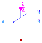
The commuting switch has a positive pin p and two negative pins n1 and n2. The switching behaviour is controlled by the inpug signal control. If control is true, the pin p is connected with the negative pin n2. Otherwise, the pin p is connected to the negative pin n1.
In order to prevent singularities during switching, the opened
switch has a (very low) conductance Goff
and the closed switch has a (very low) resistance Ron.
The limiting case is also allowed, i.e., the resistance Ron of the
closed switch could be exactly zero and the conductance Goff of the
open switch could be also exactly zero. Note, there are circuits,
where a description with zero Ron or zero Goff is not possible.
Please note:
In case of useHeatPort=true the temperature dependence of the electrical
behavior is not modelled. The parameters are not temperature dependent.
Use with care: This switch is only intended to be used for structural changes, not for fast switching sequences, due to the quasistationary formulation.
Extends from Modelica.Electrical.Analog.Interfaces.ConditionalHeatPort (Partial model to include a conditional HeatPort in order to describe the power loss via a thermal network).
| Type | Name | Default | Description |
|---|---|---|---|
| Resistance | Ron | 1.E-5 | Closed switch resistance [Ohm] |
| Conductance | Goff | 1.E-5 | Opened switch conductance [S] |
| Boolean | useHeatPort | false | =true, if HeatPort is enabled |
| Temperature | T | 293.15 | Fixed device temperature if useHeatPort = false [K] |
| Type | Name | Description |
|---|---|---|
| HeatPort_a | heatPort | |
| PositivePin | p | |
| NegativePin | n2 | |
| NegativePin | n1 | |
| input BooleanInput | control | true => p--n2 connected, false => p--n1 connected |
model IdealCommutingSwitch "Ideal commuting switch"
  import Modelica.ComplexMath.real;
  import Modelica.ComplexMath.conj;
  parameter Modelica.SIunits.Resistance Ron(final min=0)=1.E-5
    "Closed switch resistance";
  parameter Modelica.SIunits.Conductance Goff(final min=0)=1.E-5
    "Opened switch conductance";
  extends Modelica.Electrical.Analog.Interfaces.ConditionalHeatPort(final T=293.15);
  Modelica.Electrical.QuasiStationary.SinglePhase.Interfaces.PositivePin p;
  Modelica.Electrical.QuasiStationary.SinglePhase.Interfaces.NegativePin n2;
  Modelica.Electrical.QuasiStationary.SinglePhase.Interfaces.NegativePin n1;
  Modelica.Blocks.Interfaces.BooleanInput control
    "true => p--n2 connected, false => p--n1 connected";
protected
  Complex s1(re(final unit="1"), im(final unit="1"));
  Complex s2(re(final unit="1"), im(final unit="1")) "Auxiliary variables";
  constant Modelica.SIunits.ComplexVoltage  unitVoltage=
                                                       Complex(1,0);
  constant Modelica.SIunits.ComplexCurrent  unitCurrent=
                                                       Complex(1,0);
equation
  Connections.branch(p.reference, n1.reference);
  p.reference.gamma = n1.reference.gamma;
  Connections.branch(p.reference, n2.reference);
  p.reference.gamma = n2.reference.gamma;
  p.i + n2.i + n1.i = Complex(0,0);
  p.v - n1.v = (s1*unitCurrent)*(if (control) then 1 else Ron);
  n1.i = -(s1*unitVoltage)*(if (control) then Goff else 1);
  p.v - n2.v = (s2*unitCurrent)*(if (control) then Ron else 1);
  n2.i = -(s2*unitVoltage)*(if (control) then 1 else Goff);
  LossPower = real(p.v*conj(p.i)) + real(n1.v*conj(n1.i)) + real(n2.v*conj(n2.i));
end IdealCommutingSwitch;
 Modelica.Electrical.QuasiStationary.SinglePhase.Ideal.IdealIntermediateSwitch
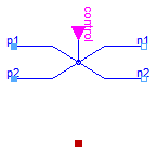
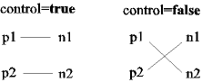
The intermediate switch has four switching contact pins p1, p2, n1, and n2. The switching behaviour is controlled by the input signal control. If control is true, the pin p1 is connected to pin n2, and the pin p2 is connected to the pin n2. Otherwise, the pin p1 is connected to n1, and p2 is connected to n2.
In order to prevent singularities during switching, the opened switch has a (very low) conductance Goff and the closed switch has a (very low) resistance Ron.
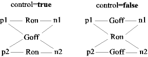
The limiting case is also allowed, i.e., the resistance Ron of the
closed switch could be exactly zero and the conductance Goff of the
open switch could be also exactly zero. Note, there are circuits,
where a description with zero Ron or zero Goff is not possible.
Please note:
In case of useHeatPort=true the temperature dependence of the electrical
behavior is not modelled. The parameters are not temperature dependent.
Use with care: This switch is only intended to be used for structural changes, not for fast switching sequences, due to the quasistationary formulation.
Extends from Modelica.Electrical.Analog.Interfaces.ConditionalHeatPort (Partial model to include a conditional HeatPort in order to describe the power loss via a thermal network).
| Type | Name | Default | Description |
|---|---|---|---|
| Resistance | Ron | 1.E-5 | Closed switch resistance [Ohm] |
| Conductance | Goff | 1.E-5 | Opened switch conductance [S] |
| Boolean | useHeatPort | false | =true, if HeatPort is enabled |
| Temperature | T | 293.15 | Fixed device temperature if useHeatPort = false [K] |
| Type | Name | Description |
|---|---|---|
| HeatPort_a | heatPort | |
| PositivePin | p1 | |
| PositivePin | p2 | |
| NegativePin | n1 | |
| NegativePin | n2 | |
| input BooleanInput | control | true => p1--n2, p2--n1 connected, otherwise p1--n1, p2--n2 connected |
model IdealIntermediateSwitch "Ideal intermediate switch"
  import Modelica.ComplexMath.real;
  import Modelica.ComplexMath.conj;
  parameter Modelica.SIunits.Resistance Ron(final min=0)=1.E-5
    "Closed switch resistance";
  parameter Modelica.SIunits.Conductance Goff(final min=0)=1.E-5
    "Opened switch conductance";
  extends Modelica.Electrical.Analog.Interfaces.ConditionalHeatPort(final T=293.15);
  Modelica.Electrical.QuasiStationary.SinglePhase.Interfaces.PositivePin p1;
  Modelica.Electrical.QuasiStationary.SinglePhase.Interfaces.PositivePin p2;
  Modelica.Electrical.QuasiStationary.SinglePhase.Interfaces.NegativePin n1;
  Modelica.Electrical.QuasiStationary.SinglePhase.Interfaces.NegativePin n2;
  Modelica.Blocks.Interfaces.BooleanInput control
    "true => p1--n2, p2--n1 connected, otherwise p1--n1, p2--n2  connected";
protected
  Complex s1(re(final unit="1"), im(final unit="1"));
  Complex s2(re(final unit="1"), im(final unit="1"));
  Complex s3(re(final unit="1"), im(final unit="1"));
  Complex s4(re(final unit="1"), im(final unit="1")) "Auxiliary variables";
  constant Modelica.SIunits.ComplexVoltage  unitVoltage=
                                                       Complex(1,0);
  constant Modelica.SIunits.ComplexCurrent  unitCurrent=
                                                       Complex(1,0);
equation
  Connections.branch(p1.reference, n1.reference);
  p1.reference.gamma = n1.reference.gamma;
  Connections.branch(p2.reference, n2.reference);
  p2.reference.gamma = n2.reference.gamma;
  Connections.branch(n1.reference, n2.reference);
  n1.reference.gamma = n2.reference.gamma;

  p1.v - n1.v = (s1*unitCurrent)*(if (control) then 1 else Ron);
  p2.v - n2.v = (s2*unitCurrent)*(if (control) then 1 else Ron);
  p1.v - n2.v = (s3*unitCurrent)*(if (control) then Ron else 1);
  p2.v - n1.v = (s4*unitCurrent)*(if (control) then Ron else 1);

  p1.i = if control then s1*unitVoltage*Goff + s3*unitCurrent else s1*unitCurrent + s3*unitVoltage*Goff;
  p2.i = if control then s2*unitVoltage*Goff + s4*unitCurrent else s2*unitCurrent + s4*unitVoltage*Goff;
  n1.i = if control then -s1*unitVoltage*Goff - s4*unitCurrent else -s1*unitCurrent - s4*unitVoltage*Goff;
  n2.i = if control then -s2*unitVoltage*Goff - s3*unitCurrent else -s2*unitCurrent - s3*unitVoltage*Goff;

  LossPower = real(p1.v*conj(p1.i)) + real(p2.v*conj(p2.i)) + real(n1.v*conj(n1.i)) + real(n2.v*conj(n2.i));
end IdealIntermediateSwitch;
 Modelica.Electrical.QuasiStationary.SinglePhase.Ideal.IdealOpeningSwitch
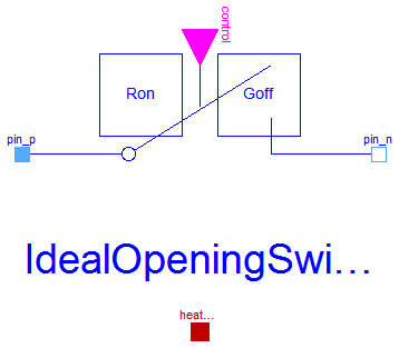
The ideal opening switch has a positive pin p and a negative pin n. The switching behaviour is controlled by the input signal control. If control is true, pin p is not connected with negative pin n. Otherwise, pin p is connected with negative pin n.
In order to prevent singularities during switching, the opened
switch has a (very low) conductance Goff
and the closed switch has a (very low) resistance Ron.
The limiting case is also allowed, i.e., the resistance Ron of the
closed switch could be exactly zero and the conductance Goff of the
open switch could be also exactly zero. Note, there are circuits,
where a description with zero Ron or zero Goff is not possible.
Please note:
In case of useHeatPort=true the temperature dependence of the electrical
behavior is not modelled. The parameters are not temperature dependent.
Use with care: This switch is only intended to be used for structural changes, not for fast switching sequences, due to the quasistationary formulation.
Extends from Modelica.Electrical.QuasiStationary.SinglePhase.Interfaces.OnePort (Two pins, current through), Modelica.Electrical.Analog.Interfaces.ConditionalHeatPort (Partial model to include a conditional HeatPort in order to describe the power loss via a thermal network).
| Type | Name | Default | Description |
|---|---|---|---|
| Resistance | Ron | 1.E-5 | Closed switch resistance [Ohm] |
| Conductance | Goff | 1.E-5 | Opened switch conductance [S] |
| Boolean | useHeatPort | false | =true, if HeatPort is enabled |
| Temperature | T | 293.15 | Fixed device temperature if useHeatPort = false [K] |
| Type | Name | Description |
|---|---|---|
| PositivePin | pin_p | Positive pin |
| NegativePin | pin_n | Negative pin |
| HeatPort_a | heatPort | |
| input BooleanInput | control | true => switch open, false => p--n connected |
model IdealOpeningSwitch "Ideal electrical opener" import Modelica.ComplexMath.real; import Modelica.ComplexMath.conj; extends Modelica.Electrical.QuasiStationary.SinglePhase.Interfaces.OnePort;parameter Modelica.SIunits.Resistance Ron(final min=0)=1.E-5 "Closed switch resistance"; parameter Modelica.SIunits.Conductance Goff(final min=0)=1.E-5 "Opened switch conductance"; extends Modelica.Electrical.Analog.Interfaces.ConditionalHeatPort(final T=293.15);Modelica.Blocks.Interfaces.BooleanInput control "true => switch open, false => p--n connected"; protected Complex s(re(final unit="1"), im(final unit="1")) "Auxiliary variable"; constant Modelica.SIunits.ComplexVoltage unitVoltage= Complex(1,0); constant Modelica.SIunits.ComplexCurrent unitCurrent= Complex(1,0); equation v = (s*unitCurrent)*(if control then 1 else Ron); i = (s*unitVoltage)*(if control then Goff else 1); LossPower = real(v*conj(i));end IdealOpeningSwitch;
 Modelica.Electrical.QuasiStationary.SinglePhase.Ideal.IdealClosingSwitch
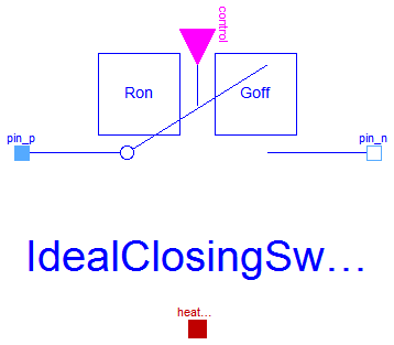
The ideal closing switch has a positive pin p and a negative pin n. The switching behaviour is controlled by input signal control. If control is true, pin p is connected with negative pin n. Otherwise, pin p is not connected with negative pin n.
In order to prevent singularities during switching, the opened
switch has a (very low) conductance Goff
and the closed switch has a (very low) resistance Ron.
The limiting case is also allowed, i.e., the resistance Ron of the
closed switch could be exactly zero and the conductance Goff of the
open switch could be also exactly zero. Note, there are circuits,
where a description with zero Ron or zero Goff is not possible.
Please note:
In case of useHeatPort=true the temperature dependence of the electrical
behavior is not modelled. The parameters are not temperature dependent.
Use with care: This switch is only intended to be used for structural changes, not for fast switching sequences, due to the quasistationary formulation.
Extends from Modelica.Electrical.QuasiStationary.SinglePhase.Interfaces.OnePort (Two pins, current through), Modelica.Electrical.Analog.Interfaces.ConditionalHeatPort (Partial model to include a conditional HeatPort in order to describe the power loss via a thermal network).
| Type | Name | Default | Description |
|---|---|---|---|
| Resistance | Ron | 1.E-5 | Closed switch resistance [Ohm] |
| Conductance | Goff | 1.E-5 | Opened switch conductance [S] |
| Boolean | useHeatPort | false | =true, if HeatPort is enabled |
| Temperature | T | 293.15 | Fixed device temperature if useHeatPort = false [K] |
| Type | Name | Description |
|---|---|---|
| PositivePin | pin_p | Positive pin |
| NegativePin | pin_n | Negative pin |
| HeatPort_a | heatPort | |
| input BooleanInput | control | true => p--n connected, false => switch open |
model IdealClosingSwitch "Ideal electrical closer" import Modelica.ComplexMath.real; import Modelica.ComplexMath.conj; extends Modelica.Electrical.QuasiStationary.SinglePhase.Interfaces.OnePort;parameter Modelica.SIunits.Resistance Ron(final min=0)=1.E-5 "Closed switch resistance"; parameter Modelica.SIunits.Conductance Goff(final min=0)=1.E-5 "Opened switch conductance"; extends Modelica.Electrical.Analog.Interfaces.ConditionalHeatPort(final T=293.15);Modelica.Blocks.Interfaces.BooleanInput control "true => p--n connected, false => switch open"; protected Complex s(re(final unit="1"), im(final unit="1")) "Auxiliary variable"; constant Modelica.SIunits.ComplexVoltage unitVoltage= Complex(1,0); constant Modelica.SIunits.ComplexCurrent unitCurrent= Complex(1,0); equation v = (s*unitCurrent)*(if control then Ron else 1); i = (s*unitVoltage)*(if control then 1 else Goff); LossPower = real(v*conj(i));end IdealClosingSwitch;