Registers is a collection of flipflops and latches. In the opposite to the Examples.Utilities models the Register models are a series of assignments in the algorithm part of the model. The model text is taken nearly identical from the standard logic text.
Extends from Modelica.Icons.Package (Icon for standard packages).
| Name | Description |
|---|---|
| Edge triggered register bank with reset | |
| Edge triggered register bank with high active reset | |
| Edge triggered register bank with low active reset | |
| Edge triggered register bank with set and reset | |
| Edge triggered register bank with high active set and reset | |
| Edge triggered register bank with low active set and reset | |
| Level sensitive register bank with reset | |
| Level sensitive register bank with reset active high | |
| Level sensitive register bank with reset active low | |
| Level sensitive register bank with set and reset | |
| Level sensitive register bank with set and reset, active high | |
| Level sensitive register bank with set and reset, active low |
 Modelica.Electrical.Digital.Registers.DFFR

Description in VHDL is given by http://www.cs.sfu.ca/~ggbaker/reference/std_logic/src/std_logic_entities
Truth Table for high active reset:
| DataIn | Clock | Reset | DataOut | Map |
| * | * | U | U | 1 |
| * | * | 1 | 0 | 2 |
| * | 0-Trns | 0 | NC | 3 |
| * | 1-Trns | 0 | DataIn | 3 |
| * | X-Trns | 0 | X or U or NC | 3 |
| * | * | X | X or U or 0 or NC | 4 |
Truth Table for low active reset:
| DataIn | Clock | Reset | DataOut | Map |
| * | * | U | U | 1 |
| * | * | 0 | 0 | 2 |
| * | 0-Trns | 1 | NC | 3 |
| * | 1-Trns | 1 | DataIn | 3 |
| * | X-Trns | 1 | X or U or NC | 3 |
| * | * | X | X or U or 0 or NC | 4 |
  *  = don't care
  U  = L.'U'
  0  = L.'0' or L.'L'
  1  = L.'1' or L.'H'
  X  = L.'X' or L.'W' or L.'Z' or L.'-'
  NC = no change

Clock transition definitions:
  1-Trns: 0 -> 1
  0-Trns: ~ -> 0 or 1 -> * or X -> X|U or U -> X|U
  X-Trns: 0 -> X|U or X|U -> 1
| Type | Name | Default | Description |
|---|---|---|---|
| Integer | ResetMap[9] | {1,4,3,2,4,4,3,2,4} | function selection, defaults for high active reset |
| Strength | strength | S.'S_X01' | output strength |
| Integer | n | 1 | data width |
| Type | Name | Description |
|---|---|---|
| input DigitalInput | reset | |
| input DigitalInput | clock | |
| input DigitalInput | dataIn[n] | |
| output DigitalOutput | dataOut[n] |
model DFFR "Edge triggered register bank with reset"
  import D = Modelica.Electrical.Digital;
  import L = Modelica.Electrical.Digital.Interfaces.Logic;
  import S = Modelica.Electrical.Digital.Interfaces.Strength;
  import T = Modelica.Electrical.Digital.Tables;
  parameter Integer ResetMap[9] = {1, 4, 3, 2, 4, 4, 3, 2, 4}
    "function selection, defaults for high active reset";
  parameter D.Interfaces.Strength strength = S.'S_X01' "output strength";
  parameter Integer n(min=1) = 1 "data width";

  D.Interfaces.DigitalInput reset;
  D.Interfaces.DigitalInput clock;
  D.Interfaces.DigitalInput dataIn[n];
  D.Interfaces.DigitalOutput dataOut[n];
protected
          Integer clock_flag(start=0);
            // 0: 0-Transition
            // 1: rising edge
            // 2: X-Transition

           Integer reset_flag(start=1);
            // 1: output := U
            // 2: output := 0
            // 3: output := -dataInUX
            // 4: output := U-0X
protected
          D.Interfaces.Logic nextstate[n](start=fill(L.'U',n));
          D.Interfaces.Logic next_assign_val[n](start=fill(L.'U',n));

algorithm
if change(clock) or change(reset) then

  if change(clock) then
    if initial() then
      clock_flag := T.ClockMap[L.'U',clock];
    else
      clock_flag := T.ClockMap[pre(clock),clock];
    end if;
  end if;

  reset_flag :=  ResetMap[reset];
  for i in 1:n loop
    if reset_flag == 1 then
      nextstate[i] := L.'U';
    elseif reset_flag == 2 then
      nextstate[i] := T.StrengthMap[L.'0', strength];
    elseif reset_flag == 3 then
      if clock_flag == 0 then
        break;
      elseif clock_flag == 1 then
        nextstate[i] := T.StrengthMap[dataIn[i], strength];
      else
        if (next_assign_val[i] == T.StrengthMap[dataIn[i], strength])
          or (next_assign_val[i] == L.'U') then
            break;
        elseif dataIn[i] == L.'U' then
            nextstate[i] := L.'U';
        else
            nextstate[i] := T.StrengthMap[L.'X', strength];
        end if;
      end if;
    elseif reset_flag == 4 then
      if (next_assign_val[i] == T.StrengthMap[L.'0', strength])
        and (dataIn[i] == L.'0' or dataIn[i] == L.'L' or clock_flag == 0) then
          break;
      elseif (dataIn[i] == L.'0' or dataIn[i] == L.'L') and (clock_flag == 1) then
          nextstate[i] := T.StrengthMap[L.'0', strength];
      elseif ((next_assign_val[i] == L.'U') and not (clock_flag == 1))
        or ((dataIn[i] == L.'U') and not (clock_flag == 0)) then
          nextstate[i] := L.'U';
      else
        nextstate[i] := T.StrengthMap[L.'X', strength];
      end if;
    end if;
  end for;
end if;
next_assign_val := nextstate;
dataOut := nextstate;
end DFFR;
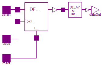
 Modelica.Electrical.Digital.Registers.DFFREG
Description in VHDL is given by http://www.cs.sfu.ca/~ggbaker/reference/std_logic/src/std_logic_entities.vhd
Truth Table
| DataIn | Clock | Reset | DataOut |
| * | * | U | U |
| * | * | 1 | 0 |
| * | 0-Trns | 0 | NC |
| * | 1-Trns | 0 | DataIn |
| * | X-Trns | 0 | X or U or NC |
| * | * | X | X or U or 0 or NC |
  *  = don't care
  U  = L.'U'
  0  = L.'0' or L.'L'
  1  = L.'1' or L.'H'
  X  = L.'X' or L.'W' or L.'Z' or L.'-'
  NC = no change

Clock transition definitions:
  1-Trns: 0 -> 1
  0-Trns: ~ -> 0 or 1 -> * or X -> X|U or U -> X|U
  X-Trns: 0 -> X|U or X|U -> 1
| Type | Name | Default | Description |
|---|---|---|---|
| Time | tHL | 0 | High->Low delay [s] |
| Time | tLH | 0 | Low->High delay [s] |
| Strength | strength | S.'S_X01' | output strength |
| Integer | n | 1 | data width |
| Type | Name | Description |
|---|---|---|
| input DigitalInput | reset | |
| input DigitalInput | clock | |
| input DigitalInput | dataIn[n] | |
| output DigitalOutput | dataOut[n] |
model DFFREG "Edge triggered register bank with high active reset"
  import D = Modelica.Electrical.Digital;
  import L = Modelica.Electrical.Digital.Interfaces.Logic;
  import S = Modelica.Electrical.Digital.Interfaces.Strength;
  import T = Modelica.Electrical.Digital.Tables;
  parameter Modelica.SIunits.Time tHL=0 "High->Low delay";
  parameter Modelica.SIunits.Time tLH=0 "Low->High delay";
  parameter D.Interfaces.Strength strength = S.'S_X01' "output strength";
  parameter Integer n(min=1) = 1 "data width";
protected
  constant Integer ResetMap[9] = {1, 4, 3, 2, 4, 4, 3, 2, 4};
      // Function selection by [reset] reading
      // 1: output := U
      // 2: output := 0
      // 3: output := -dataInUX
      // 4: output := U-0X

public
  Modelica.Electrical.Digital.Delay.InertialDelaySensitiveVector delay(
    tHL=tHL,
    tLH=tLH,
    n=n);
  D.Interfaces.DigitalInput reset;
  D.Interfaces.DigitalInput clock;
  D.Interfaces.DigitalInput dataIn[n];
  D.Interfaces.DigitalOutput dataOut[n];

  D.Registers.DFFR dFFR(n=n,
    ResetMap=ResetMap,
    strength=strength);
equation
  connect(dataOut, dataOut);
  connect(delay.y, dataOut);
  connect(dataIn, dFFR.dataIn);
  connect(dFFR.dataOut, delay.x);
  connect(clock, dFFR.clock);
  connect(reset, dFFR.reset);
end DFFREG;
Modelica.Electrical.Digital.Registers.DFFREGL
Description in VHDL is given by http://www.cs.sfu.ca/~ggbaker/reference/std_logic/src/std_logic_entities.vhd
Truth Table
| DataIn | Clock | Reset | DataOut |
| * | * | U | U |
| * | * | 0 | 0 |
| * | 0-Trns | 1 | NC |
| * | 1-Trns | 1 | DataIn |
| * | X-Trns | 1 | X or U or NC |
| * | * | X | X or U or 0 or NC |
  *  = don't care
  U  = L.'U'
  0  = L.'0' or L.'L'
  1  = L.'1' or L.'H'
  X  = L.'X' or L.'W' or L.'Z' or L.'-'
  NC = no change

Clock transition definitions:
  1-Trns: 0 -> 1
  0-Trns: ~ -> 0 or 1 -> * or X -> X|U or U -> X|U
  X-Trns: 0 -> X|U or X|U -> 1
Extends from DFFREG (Edge triggered register bank with high active reset).
| Type | Name | Default | Description |
|---|---|---|---|
| Time | tHL | 0 | High->Low delay [s] |
| Time | tLH | 0 | Low->High delay [s] |
| Strength | strength | S.'S_X01' | output strength |
| Integer | n | 1 | data width |
| Type | Name | Description |
|---|---|---|
| input DigitalInput | reset | |
| input DigitalInput | clock | |
| input DigitalInput | dataIn[n] | |
| output DigitalOutput | dataOut[n] |
model DFFREGL "Edge triggered register bank with low active reset"
  extends DFFREG(final ResetMap = {1, 4, 2, 3, 4, 4, 2, 3, 4});
      // Function selection by [reset] reading
      // 1: output := U
      // 2: output := 0
      // 3: output := -dataInUX
      // 4: output := U-0X;
end DFFREGL;
 Modelica.Electrical.Digital.Registers.DFFSR

Description in VHDL is given by http://www.cs.sfu.ca/~ggbaker/reference/std_logic/src/std_logic_entities.vhd
Truth Table for high active set and reset
| DataIn | Clock | Reset | Set | DataOut | Map |
| * | * | * | U | U | 1 |
| * | * | U | * | U | 1 |
| * | * | * | 1 | 1 | 2 |
| * | * | 1 | 0 | 0 | 3 |
| * | * | 1 | X | X | 6 |
| * | * | X | X | X or U | 4 |
| * | * | 0 | X | X or U or 1 or NC | 5 |
| * | * | X | 0 | X or U or 0 or NC | 7 |
| * | X-Trns | 0 | 0 | X or U or NC | 8 |
| * | 1-Trns | 0 | 0 | DataIn | 8 |
| * | 0-Trns | 0 | 0 | NC | 8 |
Truth Table for low active set and reset
| DataIn | Clock | Reset | Set | DataOut | Map |
| * | * | * | U | U | 1 |
| * | * | U | * | U | 1 |
| * | * | * | 0 | 1 | 2 |
| * | * | 0 | 1 | 0 | 3 |
| * | * | 0 | X | X | 6 |
| * | * | X | X | X or U | 4 |
| * | * | 1 | X | X or U or 1 or NC | 5 |
| * | * | X | 1 | X or U or 0 or NC | 7 |
| * | X-Trns | 1 | 1 | X or U or NC | 8 |
| * | 1-Trns | 1 | 1 | DataIn | 8 |
| * | 0-Trns | 1 | 1 | NC | 8 |
  *  = don't care
  ~  = not equal
  U  = L.'U'
  0  = L.'0' or L.'L'
  1  = L.'1' or L.'H'
  X  = L.'X' or L.'W' or L.'Z' or L.'-'
  NC = no change

Clock transition definitions:
  1-Trns: 0 -> 1
  0-Trns: ~ -> 0 or 1 -> * or X -> X|U or U -> X|U
  X-Trns: 0 -> X|U or X|U -> 1
| Type | Name | Default | Description |
|---|---|---|---|
| Integer | ResetSetMap[9, 9] | [1, 1, 1, 1, 1, 1, 1, 1, 1; ... | function selection by [reset, set] reading |
| Strength | strength | S.'S_X01' | output strength |
| Integer | n | 1 | data width |
| Type | Name | Description |
|---|---|---|
| input DigitalInput | set | |
| input DigitalInput | reset | |
| input DigitalInput | clock | |
| input DigitalInput | dataIn[n] | |
| output DigitalOutput | dataOut[n] |
model DFFSR "Edge triggered register bank with set and reset"
  import D = Modelica.Electrical.Digital;
  import L = Modelica.Electrical.Digital.Interfaces.Logic;
  import S = Modelica.Electrical.Digital.Interfaces.Strength;
  import T = Modelica.Electrical.Digital.Tables;
  parameter Integer ResetSetMap[9, 9]=[
             1,  1,  1,  1,  1,  1,  1,  1,  1;
             1,  4,  7,  2,  4,  4,  7,  2,  4;
             1,  5,  8,  2,  5,  5,  8,  2,  5;
             1,  6,  3,  2,  6,  6,  3,  2,  6;
             1,  4,  7,  2,  4,  4,  7,  2,  4;
             1,  4,  7,  2,  4,  4,  7,  2,  4;
             1,  5,  8,  2,  5,  5,  8,  2,  5;
             1,  6,  3,  2,  6,  6,  3,  2,  6;
             1,  4,  7,  2,  4,  4,  7,  2,  4]
    "function selection by [reset, set] reading";
    /* Defaults for set and reset are active high */
  parameter D.Interfaces.Strength strength = S.'S_X01' "output strength";
  parameter Integer n(min=1) = 1 "data width";

  D.Interfaces.DigitalInput set;
  D.Interfaces.DigitalInput reset;
  D.Interfaces.DigitalInput clock;
  D.Interfaces.DigitalInput dataIn[n];
  D.Interfaces.DigitalOutput dataOut[n];

protected
          Integer clock_flag(start=0);
            // 0: 0-Transition
            // 1: rising edge
            // 2: X-Transition

          Integer reset_set_flag(start=1);
            // 1: output := U
            // 2: output := 1
            // 3: output := 0
            // 4: output := UX
            // 5: output := -1UX
            // 6: output := X
            // 7: output := -0UX
            // 8: output := -dataInUX

          D.Interfaces.Logic nextstate[n](start=fill(L.'U',n));
          D.Interfaces.Logic next_assign_val[n](start=fill(L.'U',n));

algorithm
if change(clock) or change(reset) or change(set) then

  if change(clock) then
    if initial() then
      clock_flag := T.ClockMap[L.'U',clock];
    else
      clock_flag := T.ClockMap[pre(clock),clock];
    end if;
  end if;

  reset_set_flag := ResetSetMap[reset, set];
  for i in 1:n loop
    if reset_set_flag == 1 then
          nextstate[i] := L.'U';
    elseif reset_set_flag == 2 then
          nextstate[i] := T.StrengthMap[L.'1', strength];
    elseif reset_set_flag == 3 then
          nextstate[i] := T.StrengthMap[L.'0', strength];
    elseif reset_set_flag == 4 then
      if (next_assign_val[i] == L.'U' and clock_flag <> 1)
        or (dataIn[i] == L.'U' and clock_flag <> 0) then
          nextstate[i] := L.'U';
      else
          nextstate[i] := T.StrengthMap[L.'X', strength];
      end if;
    elseif reset_set_flag == 5 then
      if next_assign_val[i] == T.StrengthMap[L.'1', strength]
        and (dataIn[i] == L.'1' or dataIn[i] == L.'H' or clock_flag == 0) then
          break;
      elseif (dataIn[i] == L.'1' or dataIn[i] == L.'H')  and clock_flag == 1 then
          nextstate[i] := T.StrengthMap[L.'1', strength];
      elseif (next_assign_val[i] == L.'U' and clock_flag <> 1)
        or (dataIn[i] == L.'U' and clock_flag <> 0) then
          nextstate[i] := L.'U';
      else
          nextstate[i] := T.StrengthMap[L.'X', strength];
      end if;
    elseif reset_set_flag == 6 then
          nextstate[i] := T.StrengthMap[L.'X', strength];
    elseif reset_set_flag == 7 then
      if next_assign_val[i] == T.StrengthMap[L.'0', strength]
        and (dataIn[i] == L.'0' or dataIn[i] == L.'L' or clock_flag == 0) then
          break;
      elseif (dataIn[i] == L.'0' or dataIn[i] == L.'L') and clock_flag == 1 then
          nextstate[i] :=  T.StrengthMap[L.'0', strength];
      elseif (next_assign_val[i] == L.'U' and clock_flag <> 1)
        or (dataIn[i] == L.'U' and clock_flag <> 0) then
          nextstate[i] := L.'U';
      else
          nextstate[i] := T.StrengthMap[L.'X', strength];
      end if;
    elseif reset_set_flag == 8 then
      if clock_flag == 0 then
          break;
      elseif clock_flag == 1 then
          nextstate[i] := T.StrengthMap[dataIn[i], strength];
      else
        if next_assign_val[i] == T.StrengthMap[dataIn[i],strength]
        or next_assign_val[i] == L.'U' then
            break;
        elseif (dataIn[i] == L.'U') then
            nextstate[i] := L.'U';
        else
            nextstate[i] := T.StrengthMap[L.'X', strength];
        end if;
       end if;
      end if;
    end for;
  end if;

next_assign_val := nextstate;
dataOut := nextstate;
end DFFSR;
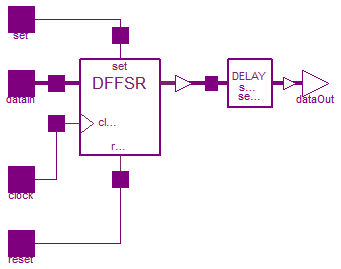
 Modelica.Electrical.Digital.Registers.DFFREGSRH
Description in VHDL is given by http://www.cs.sfu.ca/~ggbaker/reference/std_logic/src/std_logic_entities.vhd
Truth Table
| DataIn | Clock | Reset | Set | DataOut |
| * | * | * | U | U |
| * | * | U | * | U |
| * | * | * | 1 | 1 |
| * | * | 1 | 0 | 0 |
| * | * | 1 | X | X |
| * | * | X | X | X or U |
| * | * | 0 | X | X or U or 1 or NC |
| * | * | X | 0 | X or U or 0 or NC |
| * | X-Trns | 0 | 0 | X or U or NC |
| * | 1-Trns | 0 | 0 | DataIn |
| * | 0-Trns | 0 | 0 | NC |
  *  = don't care
  ~  = not equal
  U  = L.'U'
  0  = L.'0' or L.'L'
  1  = L.'1' or L.'H'
  X  = L.'X' or L.'W' or L.'Z' or L.'-'
  NC = no change

Clock transition definitions:
  1-Trns: 0 -> 1
  0-Trns: ~ -> 0 or 1 -> * or X -> X|U or U -> X|U
  X-Trns: 0 -> X|U or X|U -> 1
| Type | Name | Default | Description |
|---|---|---|---|
| Time | tHL | 0 | High->Low delay [s] |
| Time | tLH | 0 | Low->High delay [s] |
| Strength | strength | S.'S_X01' | output strength |
| Integer | n | 1 | data width |
| Type | Name | Description |
|---|---|---|
| input DigitalInput | set | |
| input DigitalInput | reset | |
| input DigitalInput | clock | |
| input DigitalInput | dataIn[n] | |
| output DigitalOutput | dataOut[n] |
model DFFREGSRH
  "Edge triggered register bank with high active set and reset"
  import D = Modelica.Electrical.Digital;
  import L = Modelica.Electrical.Digital.Interfaces.Logic;
  import S = Modelica.Electrical.Digital.Interfaces.Strength;
  import T = Modelica.Electrical.Digital.Tables;
  parameter Modelica.SIunits.Time tHL=0 "High->Low delay";
  parameter Modelica.SIunits.Time tLH=0 "Low->High delay";
  parameter D.Interfaces.Strength strength = S.'S_X01' "output strength";
  parameter Integer n(min=1) = 1 "data width";

protected
  constant Integer ResetSetMap[9, 9]=[
             1,  1,  1,  1,  1,  1,  1,  1,  1;
             1,  4,  7,  2,  4,  4,  7,  2,  4;
             1,  5,  8,  2,  5,  5,  8,  2,  5;
             1,  6,  3,  2,  6,  6,  3,  2,  6;
             1,  4,  7,  2,  4,  4,  7,  2,  4;
             1,  4,  7,  2,  4,  4,  7,  2,  4;
             1,  5,  8,  2,  5,  5,  8,  2,  5;
             1,  6,  3,  2,  6,  6,  3,  2,  6;
             1,  4,  7,  2,  4,  4,  7,  2,  4];
            // Function selection by [reset, set] reading, active high;

protected
  D.Delay.InertialDelaySensitiveVector delay(
    tHL=tHL,
    tLH=tLH,
    n=n);
  D.Registers.DFFSR dFFSR(
    strength=strength,
    n=n,
    ResetSetMap=ResetSetMap);
public
  D.Interfaces.DigitalInput set;
  D.Interfaces.DigitalInput reset;
  D.Interfaces.DigitalInput clock;
  D.Interfaces.DigitalInput dataIn[n];
  D.Interfaces.DigitalOutput dataOut[n];
equation
  connect(dFFSR.dataOut, delay.x);
  connect(set, dFFSR.set);
  connect(reset, dFFSR.reset);
  connect(clock, dFFSR.clock);
  connect(dataIn, dFFSR.dataIn);
  connect(delay.y, dataOut);
end DFFREGSRH;
Modelica.Electrical.Digital.Registers.DFFREGSRL
Description in VHDL is given by http://www.cs.sfu.ca/~ggbaker/reference/std_logic/src/std_logic_entities.vhd
Truth Table
| DataIn | Clock | Reset | Set | DataOut |
| * | * | * | U | U |
| * | * | U | * | U |
| * | * | * | 0 | 1 |
| * | * | 0 | 1 | 0 |
| * | * | 0 | X | X |
| * | * | X | X | X or U |
| * | * | 1 | X | X or U or 1 or NC |
| * | * | X | 1 | X or U or 0 or NC |
| * | X-Trns | 1 | 1 | X or U or NC |
| * | 1-Trns | 1 | 1 | DataIn |
| * | 0-Trns | 1 | 1 | NC |
  *  = don't care
  ~  = not equal
  U  = L.'U'
  0  = L.'0' or L.'L'
  1  = L.'1' or L.'H'
  X  = L.'X' or L.'W' or L.'Z' or L.'-'
  NC = no change

Clock transition definitions:
  1-Trns: 0 -> 1
  0-Trns: ~ -> 0 or 1 -> * or X -> X|U or U -> X|U
  X-Trns: 0 -> X|U or X|U -> 1
Extends from Digital.Registers.DFFREGSRH (Edge triggered register bank with high active set and reset).
| Type | Name | Default | Description |
|---|---|---|---|
| Time | tHL | 0 | High->Low delay [s] |
| Time | tLH | 0 | Low->High delay [s] |
| Strength | strength | S.'S_X01' | output strength |
| Integer | n | 1 | data width |
| Type | Name | Description |
|---|---|---|
| input DigitalInput | set | |
| input DigitalInput | reset | |
| input DigitalInput | clock | |
| input DigitalInput | dataIn[n] | |
| output DigitalOutput | dataOut[n] |
model DFFREGSRL
  "Edge triggered register bank with low active set and reset"
  extends Digital.Registers.DFFREGSRH(final ResetSetMap=[1,1,1,1,1,1,1,1,1;
        1,4,2,7,4,4,2,7,4; 1,6,2,3,6,6,2,3,6; 1,5,2,8,5,5,2,8,5; 1,4,2,7,4,
        4,2,7,4; 1,4,2,7,4,4,2,7,4; 1,6,2,3,6,6,2,3,6; 1,5,2,8,5,5,2,8,5; 1,
        4,2,7,4,4,2,7,4]);
           // Function selection by [reset, set] reading;
end DFFREGSRL;
 Modelica.Electrical.Digital.Registers.DLATR

Description in VHDL is given by http://www.cs.sfu.ca/~ggbaker/reference/std_logic/src/std_logic_entities.vhd
Truth Table for high active reset:
| DataIn | Enable | Reset | DataOut | Map |
| * | * | U | U | 1 |
| * | * | 1 | 0 | 2 |
| * | 0 | 0 | NC | 3 |
| * | 1 | 0 | DataIn | 3 |
| * | X | 0 | X or U or NC | 3 |
| * | U | ~1 | U | 4 |
| * | ~U | X | X or U or 0 or NC | 4 |
Truth Table for low active reset:
| DataIn | Enable | Reset | DataOut | Map |
| * | * | U | U | 1 |
| * | * | 0 | 0 | 2 |
| * | 0 | 1 | NC | 3 |
| * | 1 | 1 | DataIn | 3 |
| * | X | 1 | X or U or NC | 3 |
| * | U | ~0 | U | 4 |
| * | ~U | X | X or U or 0 or NC | 4 |
  *  = don't care
  ~  = not equal
  U  = L.'U'
  0  = L.'0' or L.'L'
  1  = L.'1' or L.'H'
  X  = L.'X' or L.'W' or L.'Z' or L.'-'
  NC = no change
| Type | Name | Default | Description |
|---|---|---|---|
| Integer | ResetMap[9] | {1,4,3,2,4,4,3,2,4} | function selection, defaults for high active reset |
| Strength | strength | S.'S_X01' | output strength |
| Integer | n | 1 | data width |
| Type | Name | Description |
|---|---|---|
| input DigitalInput | reset | |
| input DigitalInput | enable | |
| input DigitalInput | dataIn[n] | |
| output DigitalOutput | dataOut[n] |
model DLATR "Level sensitive register bank with reset"

  import D = Modelica.Electrical.Digital;
  import L = Modelica.Electrical.Digital.Interfaces.Logic;
  import S = Modelica.Electrical.Digital.Interfaces.Strength;
  import T = Modelica.Electrical.Digital.Tables;
  parameter Integer ResetMap[9] = {1, 4, 3, 2, 4, 4, 3, 2, 4}
    "function selection, defaults for high active reset";
  parameter D.Interfaces.Strength strength = S.'S_X01' "output strength";
  parameter Integer n(min=1) = 1 "data width";

  D.Interfaces.DigitalInput reset;
  D.Interfaces.DigitalInput enable;
  D.Interfaces.DigitalInput dataIn[n];
  D.Interfaces.DigitalOutput dataOut[n];

protected
           Integer enable_flag(start=0);
            // 0: low level
            // 1: high level
            // 2: unknown
            // 3: uninitialized

           Integer reset_flag(start=1);
            // 1: output := U
            // 2: output := 0
            // 3: output := -UdataIn
            // 4: output := U-0X

          D.Interfaces.Logic nextstate[n](start=fill(L.'U',n));
          D.Interfaces.Logic next_assign_val[n](start=fill(L.'U',n));
algorithm
  if enable == L.'1' or enable == L.'H' then
    enable_flag := 1;
  elseif enable == L.'0' or enable == L.'L' then
    enable_flag := 0;
  elseif enable == L.'U' then
    enable_flag := 3;
  else
    enable_flag := 2;
  end if;

  reset_flag :=  ResetMap[reset];
  for i in 1:n loop
    if reset_flag == 1 then
          nextstate[i] := L.'U';
    elseif reset_flag == 2 then
          nextstate[i] := T.StrengthMap[L.'0', strength];
    elseif reset_flag == 3 then
      if enable_flag == 0 then
          break;
      elseif enable_flag == 3 then
          nextstate[i] := L.'U';
      elseif enable_flag == 1 then
          nextstate[i] := T.StrengthMap[dataIn[i], strength];
      else
        if next_assign_val[i] == T.StrengthMap[dataIn[i],strength]
        or next_assign_val[i] == L.'U' then
            break;
        elseif dataIn[i] == L.'U' then
            nextstate[i] := L.'U';
        else
            nextstate[i] := T.StrengthMap[L.'X', strength];
        end if;
      end if;
    elseif reset_flag == 4 then
     if enable_flag == 3
        or (next_assign_val[i] == L.'U' and enable_flag <> 1)
        or (dataIn[i] == L.'U' and enable_flag <> 0) then
          nextstate[i] := L.'U';
      elseif next_assign_val[i] == T.StrengthMap[L.'0', strength]
        and (dataIn[i] == L.'0' or dataIn[i] == L.'L' or enable_flag == 0) then
          break;
      elseif (dataIn[i] == L.'0' or dataIn[i] == L.'L') and enable_flag == 1 then
          nextstate[i] :=  T.StrengthMap[L.'0', strength];
      else
          nextstate[i] := T.StrengthMap[L.'X', strength];
      end if;
    end if;
  end for;
  next_assign_val := nextstate;
  dataOut := nextstate;
end DLATR;
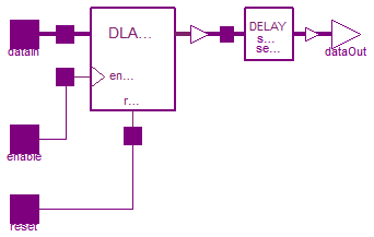
 Modelica.Electrical.Digital.Registers.DLATREG
Description in VHDL is given by http://www.cs.sfu.ca/~ggbaker/reference/std_logic/src/std_logic_entities.vhd
Truth Table
| DataIn | Enable | Reset | DataOut |
| * | * | U | U |
| * | * | 1 | 0 |
| * | 0 | 0 | NC |
| * | 1 | 0 | DataIn |
| * | X | 0 | X or U or NC |
| * | U | ~1 | U |
| * | ~U | X | X or U or 0 or NC |
  *  = don't care
  ~  = not equal
  U  = L.'U'
  0  = L.'0' or L.'L'
  1  = L.'1' or L.'H'
  X  = L.'X' or L.'W' or L.'Z' or L.'-'
  NC = no change
| Type | Name | Default | Description |
|---|---|---|---|
| Time | tHL | 0 | High->Low delay [s] |
| Time | tLH | 0 | Low->High delay [s] |
| Strength | strength | S.'S_X01' | output strength |
| Integer | n | 1 | data width |
| Type | Name | Description |
|---|---|---|
| input DigitalInput | reset | |
| input DigitalInput | enable | |
| input DigitalInput | dataIn[n] | |
| output DigitalOutput | dataOut[n] |
model DLATREG "Level sensitive register bank with reset active high"

  import D = Modelica.Electrical.Digital;
  import L = Modelica.Electrical.Digital.Interfaces.Logic;
  import S = Modelica.Electrical.Digital.Interfaces.Strength;
  import T = Modelica.Electrical.Digital.Tables;
  parameter Modelica.SIunits.Time tHL=0 "High->Low delay";
  parameter Modelica.SIunits.Time tLH=0 "Low->High delay";
  parameter D.Interfaces.Strength strength = S.'S_X01' "output strength";
  parameter Integer n(min=1) = 1 "data width";

protected
  constant Integer ResetMap[9] = {1, 4, 3, 2, 4, 4, 3, 2, 4};
      // Function selection by [reset] reading
      // 1: output := U
      // 2: output := 0
      // 3: output := -UdataIn
      // 4: output := U-0X

public
  D.Delay.InertialDelaySensitiveVector delay(
    tHL=tHL,
    tLH=tLH,
    n=n);
  D.Interfaces.DigitalInput reset;
  D.Interfaces.DigitalInput enable;
  D.Interfaces.DigitalInput dataIn[n];
  D.Interfaces.DigitalOutput dataOut[n];
  D.Registers.DLATR dLATR(n=n,
    strength=strength,
    ResetMap=ResetMap);
equation

  connect(dataOut, dataOut);
  connect(delay.y, dataOut);
  connect(dLATR.dataOut, delay.x);
  connect(dataIn, dLATR.dataIn);
  connect(enable, dLATR.enable);
  connect(reset, dLATR.reset);
end DLATREG;
Modelica.Electrical.Digital.Registers.DLATREGL
Description in VHDL is given by http://www.cs.sfu.ca/~ggbaker/reference/std_logic/src/std_logic_entities.vhd
Truth Table
| DataIn | Enable | Reset | DataOut |
| * | * | U | U |
| * | * | 0 | 0 |
| * | 0 | 1 | NC |
| * | 1 | 1 | DataIn |
| * | X | 1 | X or U or NC |
| * | U | ~0 | U |
| * | ~U | X | X or U or 0 or NC |
  *  = don't care
  ~  = not equal
  U  = L.'U'
  0  = L.'0' or L.'L'
  1  = L.'1' or L.'H'
  X  = L.'X' or L.'W' or L.'Z' or L.'-'
  NC = no change
Extends from DLATREG (Level sensitive register bank with reset active high).
| Type | Name | Default | Description |
|---|---|---|---|
| Time | tHL | 0 | High->Low delay [s] |
| Time | tLH | 0 | Low->High delay [s] |
| Strength | strength | S.'S_X01' | output strength |
| Integer | n | 1 | data width |
| Type | Name | Description |
|---|---|---|
| input DigitalInput | reset | |
| input DigitalInput | enable | |
| input DigitalInput | dataIn[n] | |
| output DigitalOutput | dataOut[n] |
model DLATREGL "Level sensitive register bank with reset active low"

  extends DLATREG(final ResetMap = {1, 4, 2, 3, 4, 4, 2, 3, 4});
      // Function selection by [reset] reading
      // 1: output := U
      // 2: output := 0
      // 3: output := -UdataIn
      // 4: output := U-0X

end DLATREGL;
 Modelica.Electrical.Digital.Registers.DLATSR

Description in VHDL is given by http://www.cs.sfu.ca/~ggbaker/reference/std_logic/src/std_logic_entities.vhd
Truth Table for high active set and reset
| DataIn | Enable | Reset | Set | DataOut | Map |
| * | * | * | U | U | 1 |
| * | * | U | ~1 | U | 1 |
| * | * | * | 1 | 1 | 2 |
| * | * | 1 | 0 | 0 | 3 |
| * | * | 1 | X | X | 6 |
| * | U | ~1 | ~1 | U | 4,5,7,8 |
| * | ~U | X | X | X or U | 4 |
| * | ~U | 0 | X | X or U or 1 or NC | 5 |
| * | ~U | X | 0 | X or U or 0 or NC | 7 |
| * | X | 0 | 0 | X or U or NC | 8 |
| * | 1 | 0 | 0 | DataIn | 8 |
| * | 0 | 0 | 0 | NC | 8 |
Truth Table for low active set and reset
| DataIn | Enable | Reset | Set | DataOut | Map |
| * | * | * | U | U | 1 |
| * | * | U | ~0 | U | 1 |
| * | * | * | 0 | 1 | 2 |
| * | * | 0 | 1 | 0 | 3 |
| * | * | 0 | X | X | 6 |
| * | U | ~0 | ~0 | U | 4,5,7,8 |
| * | ~U | X | X | X or U | 4 |
| * | ~U | 1 | X | X or U or 1 or NC | 5 |
| * | ~U | X | 1 | X or U or 0 or NC | 7 |
| * | X | 1 | 1 | X or U or NC | 8 |
| * | 1 | 1 | 1 | DataIn | 8 |
| * | 0 | 1 | 1 | NC | 8 |
  *  = don't care
  ~  = not equal
  U  = L.'U'
  0  = L.'0' or L.'L'
  1  = L.'1' or L.'H'
  X  = L.'X' or L.'W' or L.'Z' or L.'-'
  NC = no change
| Type | Name | Default | Description |
|---|---|---|---|
| Integer | ResetSetMap[9, 9] | [1, 1, 1, 1, 1, 1, 1, 1, 1; ... | function selection by [reset, set] reading |
| Strength | strength | S.'S_X01' | output strength |
| Integer | n | 1 | data width |
| Type | Name | Description |
|---|---|---|
| input DigitalInput | set | |
| input DigitalInput | reset | |
| input DigitalInput | enable | |
| input DigitalInput | dataIn[n] | |
| output DigitalOutput | dataOut[n] |
model DLATSR "Level sensitive register bank with set and reset"

  import D = Modelica.Electrical.Digital;
  import L = Modelica.Electrical.Digital.Interfaces.Logic;
  import S = Modelica.Electrical.Digital.Interfaces.Strength;
  import T = Modelica.Electrical.Digital.Tables;
  parameter Integer ResetSetMap[9, 9]=[
             1,  1,  1,  1,  1,  1,  1,  1,  1;
             1,  4,  7,  2,  4,  4,  7,  2,  4;
             1,  5,  8,  2,  5,  5,  8,  2,  5;
             1,  6,  3,  2,  6,  6,  3,  2,  6;
             1,  4,  7,  2,  4,  4,  7,  2,  4;
             1,  4,  7,  2,  4,  4,  7,  2,  4;
             1,  5,  8,  2,  5,  5,  8,  2,  5;
             1,  6,  3,  2,  6,  6,  3,  2,  6;
             1,  4,  7,  2,  4,  4,  7,  2,  4]
    "function selection by [reset, set] reading";
    /* Defaults for set and reset are active high */
  parameter D.Interfaces.Strength strength = S.'S_X01' "output strength";
  parameter Integer n(min=1) = 1 "data width";

  D.Interfaces.DigitalInput set;
  D.Interfaces.DigitalInput reset;
  D.Interfaces.DigitalInput enable;
  D.Interfaces.DigitalInput dataIn[n];
  D.Interfaces.DigitalOutput dataOut[n];

protected
          Integer enable_flag(start=0);
            // 0: low level
            // 1: high level
            // 2: unknown
            // 3: uninitialized

          Integer reset_set_flag(start=1);
            // 1: output := U
            // 2: output := 1
            // 3: output := 0
            // 4: output := UX
            // 5: output := U-1X
            // 6: output := X
            // 7: output := U-0X
            // 8: output := -UdataInX

          D.Interfaces.Logic nextstate[n](start=fill(L.'U',n));
          D.Interfaces.Logic next_assign_val[n](start=fill(L.'U',n));

algorithm
  if enable == L.'1' or enable == L.'H' then
    enable_flag := 1;
  elseif enable == L.'0' or enable == L.'L' then
    enable_flag := 0;
  elseif enable == L.'U' then
    enable_flag := 3;
  else
    enable_flag := 2;
  end if;

  reset_set_flag :=  ResetSetMap[reset, set];
  for i in 1:n loop
    if reset_set_flag == 1 then
          nextstate[i] := L.'U';
    elseif reset_set_flag == 2 then
          nextstate[i] := T.StrengthMap[L.'1', strength];
    elseif reset_set_flag == 3 then
          nextstate[i] := T.StrengthMap[L.'0', strength];
    elseif reset_set_flag == 4 then
      if enable_flag == 3
        or (next_assign_val[i] == L.'U' and enable_flag <> 1)
        or (dataIn[i] == L.'U' and enable_flag <> 0) then
          nextstate[i] := L.'U';
      else
          nextstate[i] := T.StrengthMap[L.'X', strength];
      end if;
    elseif reset_set_flag == 5 then
      if enable_flag == 3
        or (next_assign_val[i] == L.'U' and enable_flag <> 1)
        or (dataIn[i] == L.'U' and enable_flag <> 0) then
          nextstate[i] := L.'U';
      elseif next_assign_val[i] == T.StrengthMap[L.'1', strength]
        and (dataIn[i] == L.'1' or dataIn[i] == L.'H' or enable_flag == 0) then
          break;
      elseif (dataIn[i] == L.'1' or dataIn[i] == L.'H')  and enable_flag == 1 then
          nextstate[i] := T.StrengthMap[L.'1', strength];
      else
          nextstate[i] := T.StrengthMap[L.'X', strength];
      end if;
    elseif reset_set_flag == 6 then
          nextstate[i] := T.StrengthMap[L.'X', strength];
    elseif reset_set_flag == 7 then
      if enable_flag == 3
        or (next_assign_val[i] == L.'U' and enable_flag <> 1)
        or (dataIn[i] == L.'U' and enable_flag <> 0) then
          nextstate[i] := L.'U';
      elseif next_assign_val[i] == T.StrengthMap[L.'0', strength]
        and (dataIn[i] == L.'0' or dataIn[i] == L.'L' or enable_flag == 0) then
          break;
      elseif (dataIn[i] == L.'0' or dataIn[i] == L.'L') and enable_flag == 1 then
          nextstate[i] :=  T.StrengthMap[L.'0', strength];
      else
          nextstate[i] := T.StrengthMap[L.'X', strength];
      end if;
    elseif reset_set_flag == 8 then
      if enable_flag == 0 then
          break;
      elseif enable_flag == 3 then
          nextstate[i] := L.'U';
      elseif enable_flag == 1 then
          nextstate[i] := T.StrengthMap[dataIn[i], strength];
      else
        if next_assign_val[i] == T.StrengthMap[dataIn[i],strength]
        or next_assign_val[i] == L.'U' then
            break;
        elseif dataIn[i] == L.'U' then
            nextstate[i] := L.'U';
        else
            nextstate[i] := T.StrengthMap[L.'X', strength];
        end if;
      end if;
    end if;
  end for;
  next_assign_val := nextstate;
  dataOut := nextstate;
end DLATSR;
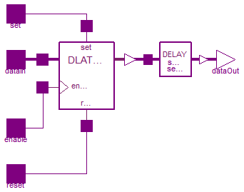
 Modelica.Electrical.Digital.Registers.DLATREGSRH
Description in VHDL is given by http://www.cs.sfu.ca/~ggbaker/reference/std_logic/src/std_logic_entities.vhd
Truth Table:
| DataIn | Enable | Reset | Set | DataOut |
| * | * | * | U | U |
| * | * | U | ~1 | U |
| * | * | * | 1 | 1 |
| * | * | 1 | 0 | 0 |
| * | * | 1 | X | X |
| * | U | ~1 | ~1 | U |
| * | ~U | X | X | X or U |
| * | ~U | 0 | X | X or U or 1 or NC |
| * | ~U | X | 0 | X or U or 0 or NC |
| * | X | 0 | 0 | X or U or NC |
| * | 1 | 0 | 0 | DataIn |
| * | 0 | 0 | 0 | NC |
  *  = don't care
  ~  = not equal
  U  = L.'U'
  0  = L.'0' or L.'L'
  1  = L.'1' or L.'H'
  X  = L.'X' or L.'W' or L.'Z' or L.'-'
  NC = no change
| Type | Name | Default | Description |
|---|---|---|---|
| Time | tHL | 0 | High->Low delay [s] |
| Time | tLH | 0 | Low->High delay [s] |
| Strength | strength | S.'S_X01' | output strength |
| Integer | n | 1 | data width |
| Type | Name | Description |
|---|---|---|
| input DigitalInput | set | |
| input DigitalInput | reset | |
| input DigitalInput | enable | |
| input DigitalInput | dataIn[n] | |
| output DigitalOutput | dataOut[n] |
model DLATREGSRH
  "Level sensitive register bank with set and reset, active high"

  import D = Modelica.Electrical.Digital;
  import L = Modelica.Electrical.Digital.Interfaces.Logic;
  import S = Modelica.Electrical.Digital.Interfaces.Strength;
  import T = Modelica.Electrical.Digital.Tables;
  parameter Modelica.SIunits.Time tHL=0 "High->Low delay";
  parameter Modelica.SIunits.Time tLH=0 "Low->High delay";
  parameter D.Interfaces.Strength strength = S.'S_X01' "output strength";
  parameter Integer n(min=1) = 1 "data width";

protected
  constant Integer ResetSetMap[9, 9]=[
             1,  1,  1,  1,  1,  1,  1,  1,  1;
             1,  4,  7,  2,  4,  4,  7,  2,  4;
             1,  5,  8,  2,  5,  5,  8,  2,  5;
             1,  6,  3,  2,  6,  6,  3,  2,  6;
             1,  4,  7,  2,  4,  4,  7,  2,  4;
             1,  4,  7,  2,  4,  4,  7,  2,  4;
             1,  5,  8,  2,  5,  5,  8,  2,  5;
             1,  6,  3,  2,  6,  6,  3,  2,  6;
             1,  4,  7,  2,  4,  4,  7,  2,  4];
            // Function selection by [reset, set] reading, active high;

public
  D.Delay.InertialDelaySensitiveVector delay(
    tHL=tHL,
    tLH=tLH,
    n=n);
  D.Interfaces.DigitalInput set;
  D.Interfaces.DigitalInput reset;
  D.Interfaces.DigitalInput enable;
  D.Interfaces.DigitalInput dataIn[n];
  D.Interfaces.DigitalOutput dataOut[n];
  D.Registers.DLATSR dLATSR(n=n,
    ResetSetMap=ResetSetMap,
    strength=strength);
equation

  connect(dataOut, dataOut);
  connect(delay.y, dataOut);
  connect(set, dLATSR.set);
  connect(reset, dLATSR.reset);
  connect(enable, dLATSR.enable);
  connect(dataIn, dLATSR.dataIn);
  connect(dLATSR.dataOut, delay.x);
end DLATREGSRH;
 Modelica.Electrical.Digital.Registers.DLATREGSRL
Description in VHDL is given by http://www.cs.sfu.ca/~ggbaker/reference/std_logic/src/std_logic_entities.vhd
Truth Table
| DataIn | Enable | Reset | Set | DataOut |
| * | * | * | U | U |
| * | * | U | ~0 | U |
| * | * | * | 0 | 1 |
| * | * | 0 | 1 | 0 |
| * | * | 0 | X | X |
| * | U | ~0 | ~0 | U |
| * | ~U | X | X | X or U |
| * | ~U | 1 | X | X or U or 1 or NC |
| * | ~U | X | 1 | X or U or 0 or NC |
| * | X | 1 | 1 | X or U or NC |
| * | 1 | 1 | 1 | DataIn |
| * | 0 | 1 | 1 | NC |
  *  = don't care
  ~  = not equal
  U  = L.'U'
  0  = L.'0' or L.'L'
  1  = L.'1' or L.'H'
  X  = L.'X' or L.'W' or L.'Z' or L.'-'
  NC = no change
Extends from Digital.Registers.DLATREGSRH (Level sensitive register bank with set and reset, active high).
| Type | Name | Default | Description |
|---|---|---|---|
| Time | tHL | 0 | High->Low delay [s] |
| Time | tLH | 0 | Low->High delay [s] |
| Strength | strength | S.'S_X01' | output strength |
| Integer | n | 1 | data width |
| Type | Name | Description |
|---|---|---|
| input DigitalInput | set | |
| input DigitalInput | reset | |
| input DigitalInput | enable | |
| input DigitalInput | dataIn[n] | |
| output DigitalOutput | dataOut[n] |
model DLATREGSRL
  "Level sensitive register bank with set and reset, active low"

  extends Digital.Registers.DLATREGSRH(final ResetSetMap=[1,1,1,1,1,1,1,1,1;
        1,4,2,7,4,4,2,7,4; 1,6,2,3,5,5,2,3,6; 1,5,2,8,6,6,2,8,5; 1,4,2,7,4,
        4,2,7,4; 1,4,2,7,4,4,2,7,4; 1,6,2,3,5,5,2,3,6; 1,5,2,8,6,6,2,8,5; 1,
        4,2,7,4,4,2,7,4]);
           // Function selection by [reset, set] reading;
end DLATREGSRL;