
Buildings.ThermalZones.EnergyPlus_24_2_0.UsersGuide
EnergyPlus package user's guide
Information

This user guide describes how to use the EnergyPlus building envelope model and exchange data during simulation between Modelica and EnergyPlus. This allows to simulate HVAC and control systems in Modelica, coupled to the EnergyPlus envelope model. The implementation is such that the joint simulation between Modelica and EnergyPlus is automatically setup, without the user having to configure a co-simulation setup. During the simulation, different data can be exchanged between Modelica and EnergyPlus.
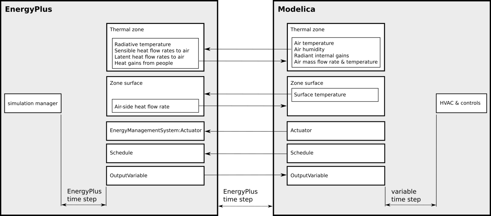
The figure above shows an overview of the exchanged coupling variables. The coupling variables can connect Modelica thermal zone model with EnergyPlus envelope model, or Modelica heat transfer models to EnergyPlus surfaces, for example to model a radiant floor. They also allow reading the value of EnergyPlus output variables for use in Modelica-implemented controllers, and writing to EnergyPlus schedules and EnergyPlus Energy Management System actuators. This can be used, for instance, to send supervisory control signals to EnergyPlus, such as for active facade control, or to control lights and equipment schedules that contribute to heat gains in the room and its surfaces.
See Buildings.ThermalZones.EnergyPlus_24_2_0.UsersGuide.Installation for how to install EnergyPlus and how EnergyPlus is invoked.
References
-
Michael Wetter, Kyle Benne, Hubertus Tummescheit and Christian Winther.
Spawn: coupling Modelica Buildings Library and EnergyPlus to enable new energy system and control applications.
Journal of Building Performance Simulation. P. 1-19. 2023. -
Michael Wetter, Kyle Benne, Antoine Gautier, Thierry S. Nouidui,
Agnes Ramle, Amir Roth, Hubertus Tummescheit, Stuart Mentzer and Christian Winther.
Lifting the Garage Door on Spawn, an Open-Source BEM-Controls Engine.
Proc. of Building Performance Modeling Conference and SimBuild, p. 518--525, Chicago, IL, USA, September 2020.
Extends from Modelica.Icons.Information (Icon for general information packages).
Package Content
| Name | Description |
|---|---|
 Installation Installation
|
Installing binaries |
| GettingStarted
|
Getting started |
| Conventions
|
Conventions |
| UnitConversion
|
Unit Conversion |
| EnergyPlusWarmUp
|
EnergyPlus warm-up |
| KnownIssues
|
Known issues |
| NotesForDymola
|
Notes for Dymola |
| AutoSizing
|
AutoSizing |
 Buildings.ThermalZones.EnergyPlus_24_2_0.UsersGuide.Installation
Installing binaries
Information
Installation of binaries
The official release of the Modelica Buildings Library that can be downloaded at simulationresearch.lbl.gov/modelica/download.html contains all binaries required to simulated the models in Buildings.ThermalZones_24_2_0. You should not have to do any other installations or settings and skip the instructions below.
However, binaries can also be downloaded and installed either using an installation script or
using a manual installation.
This is only required for users who clone the Buildings library from github.
Developers may install or build these binaries individually.
There are three different binaries:
- The Spawn of EnergyPlus library that contains a special version of EnergyPlus.
- The Modelica to EnergyPlus library that provides a layer to link Modelica with EnergyPlus.
- The fmi-library that provides the API functions that communicate with EnergyPlus.
To install or build these libraries, proceed as described below.
Spawn of EnergyPlus library
If the Buildings library is cloned from github, then the EnergyPlus libraries need to be installed by running
Buildings/Resources/src/ThermalZones/install.py --binaries-for-os-only
To install the binaries for all operating systems, omit the flag --binaries-for-os-only.
Modelica to EnergyPlus
Rebuilding this library requires CMake to be installed.
To rebuild the library, run
cd modelica-buildings
rm -rf build && mkdir build && cd build && \
  cmake ../ && cmake --build . --target install && \
  cd .. && rm -rf build
fmi-library
Rebuilding this library requires CMake to be installed.
To rebuild the library, run
cd Buildings/Resources/src/fmi-library
rm -rf build && mkdir build && \
  cd build && cmake .. && cmake --build . && \
  cd .. && rm -rf build
Manual installation of the libraries without using a script
Alternatively, instead of using install.py,
the binaries can be downloaded from the following links:
| Operating system | Link |
|---|---|
| Linux | https://spawn.s3.amazonaws.com/custom/Spawn-light-0.6.0-638b8408fd-Linux.tar.gz |
| Windows | https://spawn.s3.amazonaws.com/custom/Spawn-light-0.6.0-638b8408fd-win64.zip |
To install, proceed as follows:
| Operating system | Link |
|---|---|
| Linux |
Run from a terminal
wget https://spawn.s3.amazonaws.com/custom/Spawn-light-0.6.0-638b8408fd-Linux.tar.gz;
tar xzf Spawn-light-0.6.0-638b8408fd-Linux.tar.gz;
export PATH=${PATH}:`pwd`/Spawn-light-0.6.0-638b8408fd-Linux/bin
and restart your Modelica environment. You may put the last line in your |
| Windows |
|
How is spawn invoked?
Modelica tries to invoke spawn-0.6.0-638b8408fd[.exe] in this order:
-
On Linux, it searches for
Buildings[ x.y.z]/Resources/bin/spawn-0.6.0-638b8408fd/linux64/bin/spawn-0.6.0-638b8408fd
and on Windows, it searches forBuildings[ x.y.z]/Resources/bin/spawn-0.6.0-638b8408fd/win64/bin/spawn-0.6.0-638b8408fd.exe
whereBuildings[ x.y.z]is the installation folder of the Modelica Buildings Library. This file is distributed with the Modelica Buildings Library installation, together with all files needed to translate and simulate a model in a Modelica environment. -
If not found, it searches on the environment variable
SPAWNPATHforspawn-0.6.0-638b8408fd[.exe]. -
If not found, it searches on the environment variable
PATHforspawn-0.6.0-638b8408fd[.exe].
If none of this succeeds, it will stop with an error.
Extends from Modelica.Icons.Information (Icon for general information packages).
Modelica definition
Buildings.ThermalZones.EnergyPlus_24_2_0.UsersGuide.GettingStarted
Getting started
Information
How to instantiate models for one or several buildings
To instantiate one or several building models, proceed as follows:
-
Create an instance of
Buildings.ThermalZones.EnergyPlus_24_2_0.Building to specify the building model.
This instance is automatically named
buildingand this name must not be changed. -
In the instance
building, specify building-level parameters such as the EnergyPlus input file name and weather file name. -
For the weather file, both
.mosand.epwfiles must be specified. The.epwfile will be used by the EnergyPlus envelope model, and the.mosfile will be used by the Modelica model, and must be specified by the parametersepwNameandweaNamein the instancebuilding.
The following coupling objects can then be integrated in the model that contains the instance
building, or in any model instantiated by that model.
- To connect Modelica zone models with the equivalent EnergyPlus zone envelopes, instantiate any number of Buildings.ThermalZones.EnergyPlus_24_2_0.ThermalZone models and parameterize them with the name of the thermal zones as they are entered in the EnergyPlus input data file. Each model should also be assigned the medium of heat transfer (typically air), as is done for any other fluid flow component.
- To write to EnergyPlus actuators or schedules during the simulation, instantiate any number of Buildings.ThermalZones.EnergyPlus_24_2_0.Actuator or Buildings.ThermalZones.EnergyPlus_24_2_0.Schedule models.
- To retrieve the current values of output variables from EnergyPlus, instantiate any number of Buildings.ThermalZones.EnergyPlus_24_2_0.OutputVariable models.
- To model an opaque construction such as a radiant slab in Modelica and interface it to EnergyPlus, instantiate any number of Buildings.ThermalZones.EnergyPlus_24_2_0.OpaqueConstruction models.
- To set individual surface temperatures in EnergyPlus and retrieve their room-side heat gains, instantiate any number of Buildings.ThermalZones.EnergyPlus_24_2_0.ZoneSurface models.
If you have more than one building, you can repeat the above steps for each building and combine these building models in a top-level model. See for example Buildings.ThermalZones.EnergyPlus_24_2_0.Validation.MultipleBuildings.ThreeZonesTwoBuildings for how to combine two buildings in one Modelica model.
For details of how to configure these models, see the information section of these models, and look at the example models below.
Example models
To get started, we recommend to look at the simple examples in Buildings.ThermalZones.EnergyPlus_24_2_0.Examples.SingleFamilyHouse which illustrate the use of all these objects based on a single family house. Also, read the information section of the models you plan to use in Buildings.ThermalZones.EnergyPlus_24_2_0.
We suggest looking at the examples in the following order which starts with the simplest example and moves to more comprehensive ones.
- Buildings.ThermalZones.EnergyPlus_24_2_0.Examples.SingleFamilyHouse.Unconditioned is modeling one zone, the living room, in Modelica as an unconditioned zone with a fixed amount of outside air infiltration.
- Buildings.ThermalZones.EnergyPlus_24_2_0.Examples.SingleFamilyHouse.AirHeating adds an air-based heating system that recirculates air to track a heating setpoint temperature.
- Buildings.ThermalZones.EnergyPlus_24_2_0.Examples.SingleFamilyHouse.EquipmentSchedule shows how to set the equipment schedule in Modelica and override the schedule in EnergyPlus. It also uses the unconditioned thermal zone to keep it simple.
- Buildings.ThermalZones.EnergyPlus_24_2_0.Examples.SingleFamilyHouse.LightsControl is showing how to set the value of an EMS Actuator, here the one that sets internal gains caused by the lights which are controlled by Modelica based on time of day and sun position. The model also shows how to read an EnergyPlus output variable, here for the lighting electricity consumption.
- Buildings.ThermalZones.EnergyPlus_24_2_0.Examples.SingleFamilyHouse.ShadeControl reads from EnergyPlus the incident solar radiation, retrieves from the thermal zone its temperature, and based on these values, actuates the window shading control using an EMS actuator.
- Buildings.ThermalZones.EnergyPlus_24_2_0.Examples.SingleFamilyHouse.RadiantHeatingCooling_TSurface and Buildings.ThermalZones.EnergyPlus_24_2_0.Examples.SingleFamilyHouse.RadiantHeatingCooling_TRoom illustrate how to couple a radiant slab for heating and cooling which interfaces two surfaces in EnergyPlus: The floor that connects the slab to the zone above, and the ceiling that connects the slab to the zone below. In the first model, cooling is controlled based on the surface temperature, and in the second model, it is controlled based on the room temperature.
- Buildings.ThermalZones.EnergyPlus_24_2_0.Examples.SingleFamilyHouse.HeatPumpRadiantHeatingGroundHeatTransfer illustrates how to couple a radiant slab for heating in a configuration in which the bottom of the slab is connected to a ground heat transfer model in Modelica. Heating is provided with a geothermal heat pump that is connected to a borehole heat exchanger.
- Buildings.ThermalZones.EnergyPlus_24_2_0.Examples.SingleFamilyHouse.Radiator shows how to couple a radiator to a thermal zone.
Extends from Modelica.Icons.Information (Icon for general information packages).
Modelica definition
Buildings.ThermalZones.EnergyPlus_24_2_0.UsersGuide.Conventions
Conventions
Information
Conventions
The following conventions are made:
-
The entries of the EnergyPlus
RunPeriodobject are ignored. See Buildings.ThermalZones.EnergyPlus_24_2_0.Data.RunPeriod for how the run period and the day of the week are handled. - In EnergyPlus, a year of simulation always has 365 days, i.e., leap years are not considered. This is done because in the Modelica Buildings Library, weather files are assumed to have a periodicity of 365 days.
-
If a zone is in the idf file but not modeled in Modelica, then
- EnergyPlus will simulate the zone as free floating, and
- EnergyPlus will simulate the outside air infiltration if specified in the idf file.
- If a zone is in the idf file and modeled in Modelica using Buildings.ThermalZones.EnergyPlus_24_2_0.ThermalZone, then EnergyPlus will remove all infiltration objects for this zone. This is done because Modelica computes the mass balance of the zone air, and infiltration depends on the static pressure of the HVAC system. Pressure-driven infiltration can be modeled using Buildings.Airflow.Multizone, or a fixed infiltration rate can be imposed as is shown in Buildings.ThermalZones.EnergyPlus_24_2_0.Examples.SingleFamilyHouse.AirHeating.
- All EnergyPlus HVAC objects that are present in the idf file are removed when coupled to Spawn.
- Output variables and EMS actuators need not be present in the idf file.
- For the EnergyPlus envelope, either the CTF transfer function or the finite difference method can be used.
- The coupling time step is determined by EnergyPlus based on the zone time step, as declared in the idf file.
- In EnergyPlus, a year of simulation always has 365 days, i.e., leap years are not considered. This is done because in the Modelica Buildings Library, weather files are assumed to have a periodicity of 365 days.
Extends from Modelica.Icons.Information (Icon for general information packages).
Modelica definition
Buildings.ThermalZones.EnergyPlus_24_2_0.UsersGuide.UnitConversion
Unit Conversion
Information
Unit conversion
Units between Modelica and EnergyPlus are automatically converted, if they are specified. The conversion is according to the table at Buildings.ThermalZones.EnergyPlus_24_2_0.Types.Units.
To see what units are used, set printUnits=true (the default) in the
instance
Buildings.ThermalZones.EnergyPlus_24_2_0.Building.
This will cause the used units to be reported in the Modelica log file.
The thermal zone model automatically converts the units.
To do unit conversion for values sent by
Buildings.ThermalZones.EnergyPlus_24_2_0.Actuator
and by
Buildings.ThermalZones.EnergyPlus_24_2_0.Schedule,
set the parameter unit to the unit of the variable obtained at
the input connector u. The value will then be converted
before it is sent to EnergyPlus.
The units that are used in the input u of this block
are reported to the Modelica log file.
To do unit conversion for values read by
Buildings.ThermalZones.EnergyPlus_24_2_0.OutputVariable,
Modelica will use the units reported by EnergyPlus.
The units that are used in the output y of this block
are reported to the Modelica log file.
Extends from Modelica.Icons.Information (Icon for general information packages).
Modelica definition
Buildings.ThermalZones.EnergyPlus_24_2_0.UsersGuide.EnergyPlusWarmUp
EnergyPlus warm-up
Information
EnergyPlus warm-up
In Spawn there can be both connected and unconnected zones defined in the EnergyPlus input file. Connected zones have a corresponding zone model Buildings.ThermalZones.EnergyPlus_24_2_0.ThermalZone in Modelica that communicates with the EnergyPlus zone heat balance model. Unconnected zones are thermal zones which are defined entirely within the EnergyPlus input file, and for these zones the conventional EnergyPlus algorithms are used to simulate the zone conditions, including the air temperature and humidity, which are free floating. In contrast, for connected zones, Modelica models the temperature and humidity. During the initialization of a new simulation it is necessary to compute initial values for the zone air conditions as well as the conditions of any thermal mass, such as for walls, floors and ceilings. Conventionally, EnergyPlus handles this requirement using a warmup period, and in Spawn the traditional EnergyPlus warmup algorithm is employed to initialize unconnected zones. The EnergyPlus warmup algorithm is described in the EnergyPlus Engineering Reference, and summarized in the following steps.
-
Zone and wall surface temperatures are initialized to 23°C.
-
Zone humidity ratios are initialized to the outdoor conditions.
-
During warmup, the outdoor conditions are determined by the EnergyPlus weather file.
-
The first day of the simulation is repeated until warmup convergence, which occurs when the minimum and maximum air temperatures during the warmup day remain nearly the same between two successive iterations.
Spawn initializes unconnected zones using the warmup algorithm that was just described. However, connected zones are treated differently than in a conventional EnergyPlus simulation because initial zone air properties are specified in the Modelica zone model. During Spawn warmup, the following steps occur:
-
All wall surface temperatures are initialized to 23°C just as they are in a conventional EnergyPlus warmup period. However, as in EnergyPlus, during the warmup iterations, the exterior walls will be subject to the ambient conditions defined by the weather file. Therefore, exterior surface temperatures will not remain fixed at their 23°C initial condition during the warmup process. Similarly, room-facing wall surfaces will be exposed to the zone temperature, and therefore approach a quasi-steady state at the conclusion of warmup.
-
The air temperatures of unconnected zones are initialized to 23°C.
-
The humidity ratios of unconnected zones are initialized to the outdoor conditions.
-
The air temperatures and humidity ratios of connected zones are initialized to the initial values defined in Modelica, and held fixed during the warmup period.
-
During warmup, the outdoor conditions are determined by the EnergyPlus weather file in the same way as a conventional EnergyPlus simulation.
-
The first day of the simulation is repeated, but Spawn uses a different criteria for stopping the iteration compared to a conventional EnergyPlus simulation. In EnergyPlus, the first day is repeated until the zone air temperature reaches a periodic steady state as indicated by the minimum and maximum temperatures for the warmup day stabilizing. In Spawn, the exit criteria is similarly based on reaching a periodic steady state, however Spawn exits warmup when the surface temperatures stabilize instead of the air temperature.
Extends from Modelica.Icons.Information (Icon for general information packages).
Modelica definition
Buildings.ThermalZones.EnergyPlus_24_2_0.UsersGuide.KnownIssues
Known issues
Information
Known issues
Signals to time schedules and actuators
If Modelica overrides a time schedule or an actuator at a time instant that does not
coincide with an EnergyPlus time step, the change in value may be ignored for the heat balance
of the current EnergyPlus time step.
This will be addressed through
issue 2000.
Running Spawn from a directory with spaces
Spawn stops with an error message if run from a directory that contains spaces (because loading the FMU would fail). Therefore, make sure the working directory has no spaces. The installation directory of the Buildings library however is allowed to have spaces.
This error check has been introduced in issue 3993.
Extends from Modelica.Icons.Information (Icon for general information packages).
Modelica definition
Buildings.ThermalZones.EnergyPlus_24_2_0.UsersGuide.NotesForDymola
Notes for Dymola
Information
Notes for Dymola
64 bit configuration
Make sure Dymola compiles in 64 bit, which can be done by setting the flag
Advanced.CompileWith64 = 2
Otherwise, you may get an error such as
/usr/bin/ld: cannot find -lfmilib_shared
collect2: error: ld returned 1 exit status
Extends from Modelica.Icons.Information (Icon for general information packages).
Modelica definition
Buildings.ThermalZones.EnergyPlus_24_2_0.UsersGuide.AutoSizing
AutoSizing
Information
AutoSizing
Autosizing in Spawn of EnergyPlus is implemented to help users automatically size system equipment and components modeled in Modelica using sizing capabilities in EnergyPlus. The general workflow is to specify sizing objects in the idf file that are typically used in EnergyPlus workflows and propagate values from pre-defined sizing parameters in Modelica, whose values are obtained from the EnergyPlus sizing process during initialization, throughout the model as-needed. More information about setting up autosizing and the pre-defined sizing parameters is described below.
Autosizing for Zones and Systems in Modelica
The process for setting up autosizing in Modelica is as follows, with related notes:
-
Instantiate an instance of class
Buildings.ThermalZones.EnergyPlus_24_2_0.SystemSizing.
-
Name the autosize system using the string parameter
hvacSystemName. -
Toggle the boolean parameter
autosizeHVAC=true.
-
Name the autosize system using the string parameter
-
Add thermal zones to be autosized as part of the autosize system instantiated
in the previous step by specifying the string parameter
hvacSystemNamein the thermal zone object so that it matches the name given to the system in the previous step.- You may assign multiple zones to the same autosize system.
-
The value of the boolean parameter
autosizeHVACin the autosize system object will apply to all thermal zones specified as part of that system. - The sizing values returned for each zone are for the design condition of each zone individually, while the sizing values returned for each system are for the design condition of the system considering the coincident load from each zone that is part of that system.
- Any zone not assigned to a system will not be autosized.
Pre-defined Sizing Parameters in Modelica
The results of autosizing from EnergyPlus are populated into Modelica records that are accessible at the zone and system levels. Two records exist that contain the same parameters: one for heating and one for cooling.
The zone level records are:
- Buildings.ThermalZones.EnergyPlus_24_2_0.ThermalZone.sizHea
- Buildings.ThermalZones.EnergyPlus_24_2_0.ThermalZone.sizCoo
The system level records are:
- Buildings.ThermalZones.EnergyPlus_24_2_0.SystemSizing.sizHea
- Buildings.ThermalZones.EnergyPlus_24_2_0.SystemSizing.sizCoo
The parameters available within these records are:
-
QSen_flow: Design sensible load [W] (if not sized, equals 0) -
QLat_flow: Design latent load [W] (if not sized, equals 0) -
TSet: Indoor temperature set point at the design load [K] (if not sized, equals 0°C for zone heating and cooling, -273.15°C for system group heating and cooling) -
XSet: Indoor humidity ratio set point at the design load per total air mass [kg/kg] (if not sized, equals 0) -
TOut: Outdoor drybulb temperature at the design load [K] (if not sized, equals 0°C for zone heating and cooling, 21°C for system group heating and cooling) -
XOut: Outdoor humidity ratio at the design load per total air mass [kg/kg] (if not sized, equals 0) -
mOut_flow: Minimum outdoor air flow rate during the design load [kg/s] (if not sized, equals 0) -
t: Time within the sizing day at which the design load occurred [s] (if not sized, equals 0)
Other Notes
Infiltration: All zone air infiltration for thermal zones connected
to EnergyPlus is implemented
in Modelica, and any infiltration information for these zones
in the .idf is ignored during autosizing. For zones
in the .idf not connected to Modelica thermal zones, infiltration information
is still utilized during autosizing.
For autosizing zones in Modelica connected to EnergyPlus,
zone air infiltration can be considered
using the parameter ThermalZone.airChaRatInf, which
will add sensible and latent infiltration loads to the design zone heating
and cooling loads at the specified air exchange rate using the temperature
and humidity ratio zone set points and outdoor air conditions at the time of the zone
design loads. The infiltration loads will also be added to the system level
from each zone that is part of the system, with each zone's contribution calculated
using the outdoor air conditions for the system level design load and each zone's
zone level set points.
Internal Gains: Internal gain objects for people, lights, and equipment in the .idf are considered by EnergyPlus during autosizing, and are thus reflected in the sizing results returned to Modelica. If internal gain inputs are specified in Modelica, they are ignored during autosizing, but used in place of .idf objects during simulation.
Interzonal Air Exchange: All interzonal air exchange is implemented in Modelica, and any interzonal air exchange information in the .idf is ignored during both autosizing and simulation.
Thermostat and Humidistat Controls: Spawn uses thermostat and humidistat controls specified in the .idf for autosizing thermal zones connected to Modelica. For thermal zones connected to Modelica that do not have thermostat nor humidistat controls specified in the .idf, Spawn automatically adds a dual-setpoint thermostat with heating and cooling set points of 20°C and 22°C respectively and a dual-set point humidistat with humidifying and dehumidifying relative humidity set points of 45% and 55% respectively.
References for Autosizing in EnergyPlus: Autosizing objects in the .idf are used to direct the autosizing in Spawn, and the EnergyPlus algorithms are followed for the sizing calculations. However, note that Spawn replaces the SimulationControl object specified in the .idf to invoke autosizing on its own. Some useful references for working with those objects and setting up sizing in the .idf are as follows:
- Zone sizing: https://bigladdersoftware.com/epx/docs/24-2/engineering-reference/zone-design-loads-and-air-flow-rates.html
- System sizing: https://bigladdersoftware.com/epx/docs/24-2/engineering-reference/system-design-loads-and-air-flow-rates.html
- Sizing manager and algorithm: https://bigladdersoftware.com/epx/docs/24-2/engineering-reference/sizing-manager.html
Example Models
- Buildings.ThermalZones.EnergyPlus_24_2_0.Examples.SingleFamilyHouse.AirHeating_Autosizing
- Buildings.ThermalZones.EnergyPlus_24_2_0.Examples.SmallOffice.IdealHeatingCoolingWinter_Autosizing
- Buildings.ThermalZones.EnergyPlus_24_2_0.Examples.SmallOffice.IdealHeatingCoolingSummer_Autosizing
- Buildings.ThermalZones.EnergyPlus_24_2_0.Examples.SmallOffice.ASHRAE2006Winter_Autosizing
- Buildings.ThermalZones.EnergyPlus_24_2_0.Examples.SmallOffice.ASHRAE2006Summer_Autosizing
- Buildings.ThermalZones.EnergyPlus_24_2_0.Examples.SmallOffice.Guideline36Winter_Autosizing
- Buildings.ThermalZones.EnergyPlus_24_2_0.Examples.SmallOffice.Guideline36Summer_Autosizing
Extends from Modelica.Icons.Information (Icon for general information packages).