Buildings.Obsolete.Examples.VAVReheat.BaseClasses
Package with base classes
Information
This package contains base classes.
Extends from Modelica.Icons.BasesPackage (Icon for packages containing base classes).
Package Content
| Name | Description |
|---|---|
| Variable air volume flow system with terminal reheat and Guideline 36 control sequence serving five thermal zones | |
| Supply branch of a VAV system |
 Buildings.Obsolete.Examples.VAVReheat.BaseClasses.Guideline36
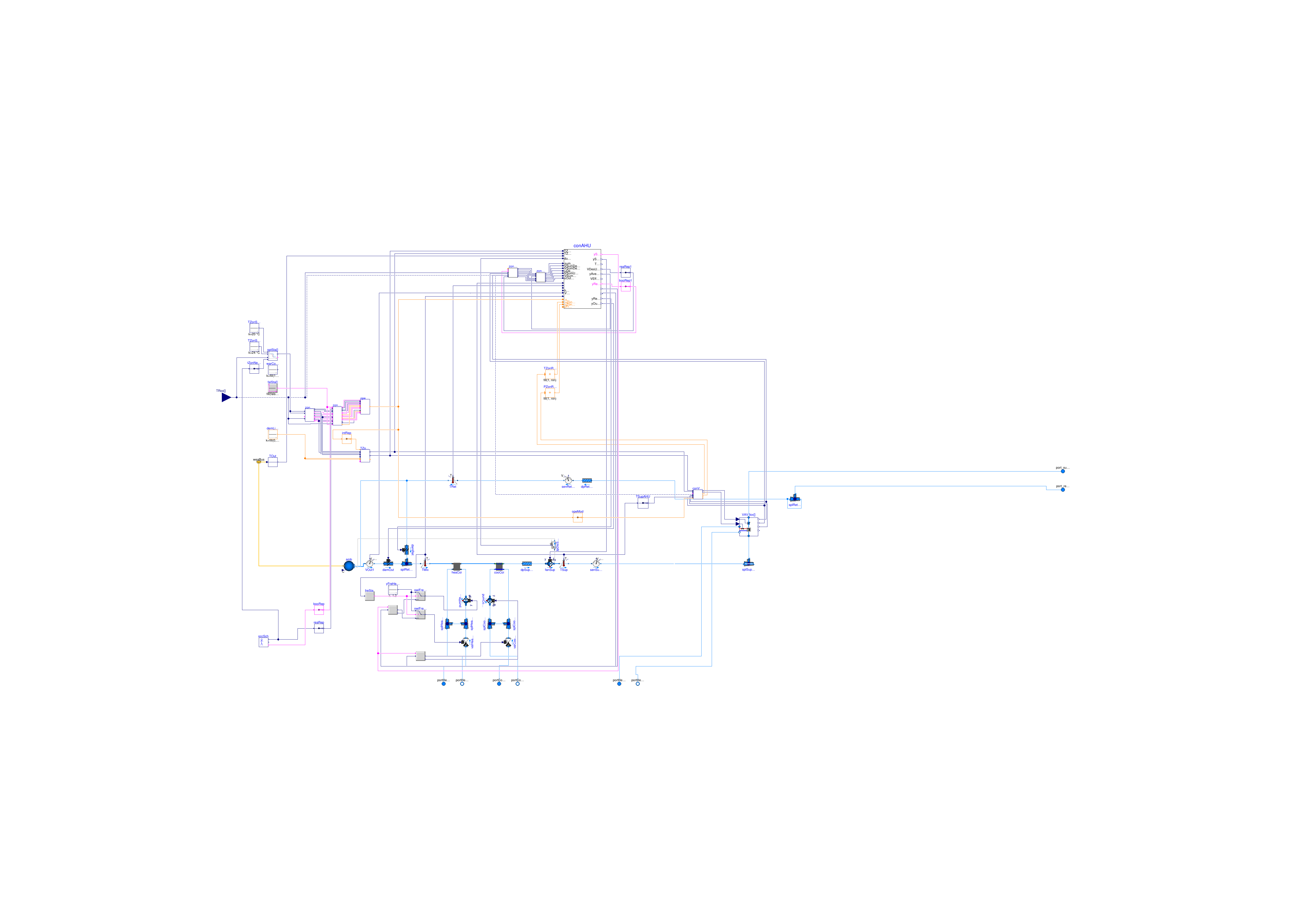
Variable air volume flow system with terminal reheat and Guideline 36 control sequence serving five thermal zones

Information
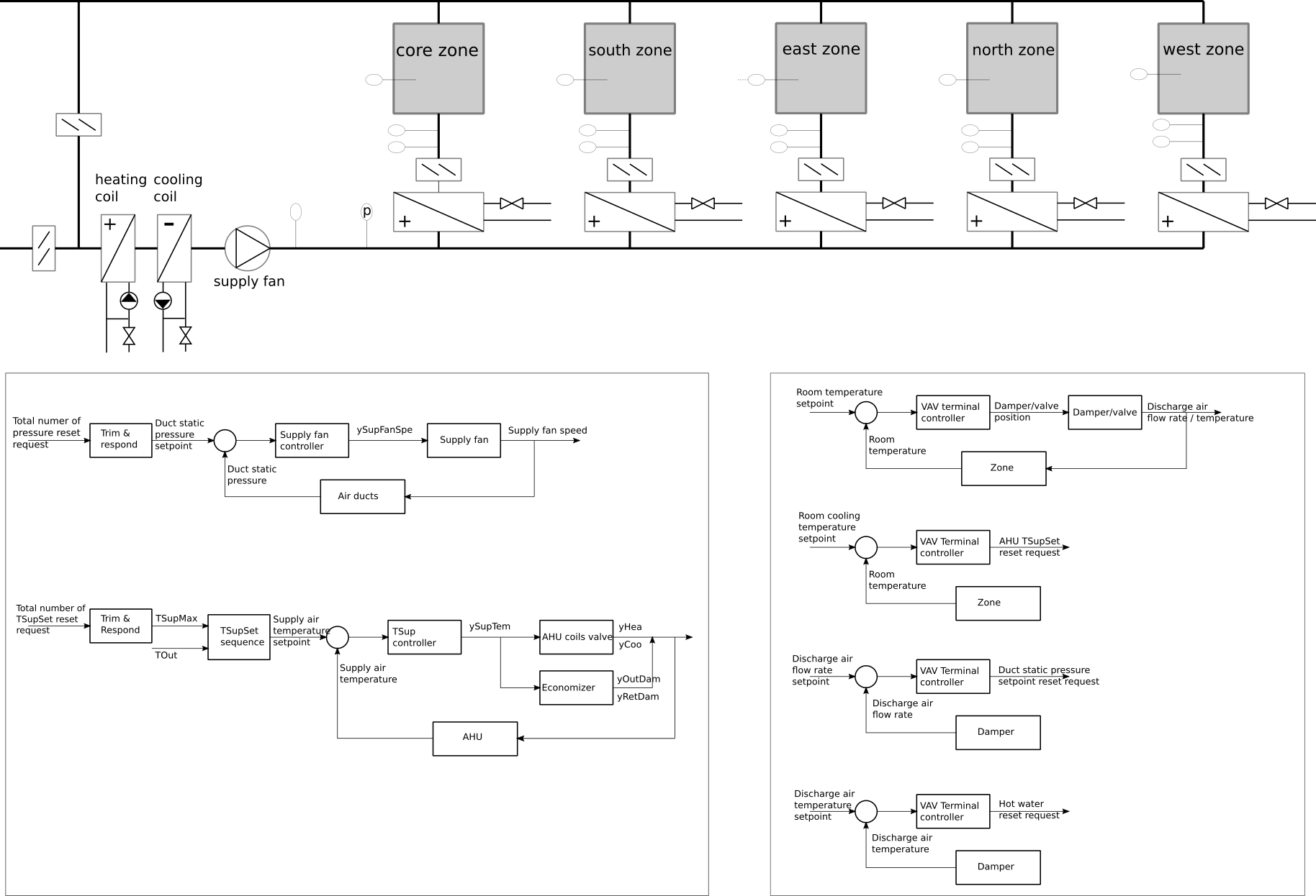
This model consist of an HVAC system is a variable air volume (VAV) flow system with economizer and a heating and cooling coil in the air handler unit. There is also a reheat coil and an air damper in each of the five zone inlet branches.
See the model Buildings.Examples.VAVReheat.BaseClasses.PartialHVAC for a description of the HVAC system.
The control is based on ASHRAE Guideline 36, and implemented using the sequences from the library Buildings.Obsolete.Controls.OBC.ASHRAE.G36_PR1 for multi-zone VAV systems with economizer. The figures below shows the schematic diagram and controls of an HVAC system that supplies 5 zones:

A similar model but with a different control sequence can be found in Buildings.Examples.VAVReheat.ASHRAE2006. Note that this model, because of the frequent time sampling, has longer computing time than Buildings.Examples.VAVReheat.ASHRAE2006. The reason is that the time integrator cannot make large steps because it needs to set a time step each time the control samples its input.
Extends from Buildings.Examples.VAVReheat.BaseClasses.PartialHVAC (Partial model of variable air volume flow system with terminal reheat that serves five thermal zones).
Parameters
| Type | Name | Default | Description |
|---|---|---|---|
| replaceable package MediumA | Air | Medium model for air | |
| replaceable package MediumW | Water | Medium model for water | |
| Volume | VRoo[numZon] | Room volume per zone [m3] | |
| Area | AFlo[numZon] | Floor area per zone [m2] | |
| HeatFlowRate | QHeaAHU_flow_nominal | mHeaAir_flow_nominal*cpAir*(... | Nominal heating heat flow rate of air handler unit coil [W] |
| HeatFlowRate | QCooAHU_flow_nominal | 1.3*mCooAir_flow_nominal*cpA... | Nominal total cooling heat flow rate of air handler unit coil (negative number) [W] |
| Real | ratOAFlo_A | 0.3e-3 | Outdoor airflow rate required per unit area [m3/(s.m2)] |
| Real | ratOAFlo_P | 2.5e-3 | Outdoor airflow rate required per person |
| Real | ratP_A | 5e-2 | Occupant density |
| Real | effZ | 0.8 | Zone air distribution effectiveness (limiting value) [1] |
| Real | divP | 0.7 | Occupant diversity ratio [1] |
| VolumeFlowRate | VZonOA_flow_nominal[numZon] | (ratOAFlo_P*ratP_A + ratOAFl... | Zone outdoor air flow rate of each VAV box [m3/s] |
| VolumeFlowRate | Vou_flow_nominal | (divP*ratOAFlo_P*ratP_A + ra... | System uncorrected outdoor air flow rate [m3/s] |
| Real | effVen | if divP < 0.6 then 0.88*divP... | System ventilation efficiency [1] |
| VolumeFlowRate | Vot_flow_nominal | Vou_flow_nominal/effVen | System design outdoor air flow rate [m3/s] |
| PressureDifference | dpBuiStaSet | 12 | Building static pressure [Pa] |
| Real | yFanMin | 0.1 | Minimum fan speed |
| Boolean | allowFlowReversal | true | = false to simplify equations, assuming, but not enforcing, no flow reversal |
| VolumeFlowRate | minZonPriFlo[numZon] | conVAV.VDisSetMin_flow | Minimum expected zone primary flow rate [m3/s] |
| Time | samplePeriod | 120 | Sample period of component, set to the same value as the trim and respond that process yPreSetReq [s] |
| PressureDifference | dpDisRetMax | 40 | Maximum return fan discharge static pressure setpoint [Pa] |
| Nominal mass flow rate | |||
| MassFlowRate | mCooVAV_flow_nominal[numZon] | Design mass flow rate per zone for cooling [kg/s] | |
| MassFlowRate | mHeaVAV_flow_nominal[numZon] | 0.3*mCooVAV_flow_nominal | Design mass flow rate per zone for heating [kg/s] |
| MassFlowRate | mAir_flow_nominal | mCooAir_flow_nominal | Nominal mass flow rate for fan [kg/s] |
| MassFlowRate | mCooAir_flow_nominal | 0.7*sum(mCooVAV_flow_nominal) | Nominal mass flow rate for fan [kg/s] |
| MassFlowRate | mHeaAir_flow_nominal | 0.7*sum(mHeaVAV_flow_nominal) | Nominal mass flow rate for fan [kg/s] |
| MassFlowRate | mHeaWat_flow_nominal | QHeaAHU_flow_nominal/cpWat/10 | Nominal water mass flow rate for heating coil in AHU [kg/s] |
| MassFlowRate | mCooWat_flow_nominal | QCooAHU_flow_nominal/cpWat/(... | Nominal water mass flow rate for cooling coil [kg/s] |
| Room temperature setpoints | |||
| Temperature | THeaOn | 293.15 | Heating setpoint during on [K] |
| Temperature | THeaOff | 285.15 | Heating setpoint during off [K] |
| Temperature | TCooOn | 297.15 | Cooling setpoint during on [K] |
| Temperature | TCooOff | 303.15 | Cooling setpoint during off [K] |
| Air handler unit nominal temperatures and humidity | |||
| Temperature | TCooAirMix_nominal | 303.15 | Mixed air temperature during cooling nominal conditions (used to size cooling coil) [K] |
| Temperature | TCooAirSup_nominal | 285.15 | Supply air temperature during cooling nominal conditions (used to size cooling coil) [K] |
| MassFraction | wCooAirMix_nominal | 0.017 | Humidity ratio of mixed air at a nominal conditions used to size cooling coil (in kg/kg dry total) [1] |
| Temperature | TCooWatInl_nominal | 279.15 | Cooling coil nominal inlet water temperature [K] |
| Temperature | THeaAirMix_nominal | 277.15 | Mixed air temperature during heating nominal conditions (used to size heating coil) [K] |
| Temperature | THeaAirSup_nominal | 285.15 | Supply air temperature during heating nominal conditions (used to size heating coil) [K] |
| Temperature | THeaWatInl_nominal | Reheat coil nominal inlet water temperature [K] | |
Connectors
| Type | Name | Description |
|---|---|---|
| FluidPort_a | port_supAir[numZon] | Supply air to thermal zones |
| FluidPort_a | port_retAir[numZon] | Return air from thermal zones |
| input RealInput | TRoo[numZon] | Room temperatures [K] |
| Bus | weaBus | Weather data bus |
| FluidPort_a | portHeaCoiSup | Heating coil loop supply |
| FluidPort_b | portHeaCoiRet | Heating coil loop return |
| FluidPort_a | portHeaTerSup | Terminal heat loop supply |
| FluidPort_b | portHeaTerRet | Terminal heat loop return |
| FluidPort_a | portCooCoiSup | Cooling coil loop supply |
| FluidPort_b | portCooCoiRet | Coolin coil loop return |
Modelica definition
 Buildings.Obsolete.Examples.VAVReheat.BaseClasses.VAVBranch
Supply branch of a VAV system

Information
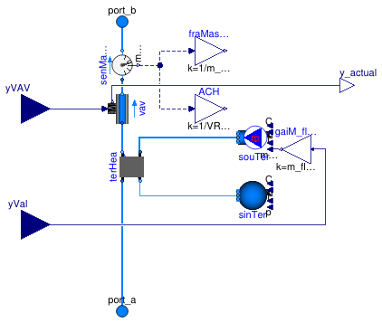
Model for a VAV supply branch. The terminal VAV box has a pressure independent damper and a water reheat coil. The pressure independent damper model includes an idealized flow rate controller and requires a discharge air flow rate set-point (normalized to the nominal value) as a control signal.
Extends from Modelica.Blocks.Icons.Block (Basic graphical layout of input/output block).
Parameters
| Type | Name | Default | Description |
|---|---|---|---|
| replaceable package MediumA | Modelica.Media.Interfaces.Pa... | Medium model for air | |
| replaceable package MediumW | Modelica.Media.Interfaces.Pa... | Medium model for water | |
| Boolean | allowFlowReversal | true | = false to simplify equations, assuming, but not enforcing, no flow reversal |
| MassFlowRate | m_flow_nominal | Mass flow rate of this thermal zone [kg/s] | |
| Volume | VRoo | Room volume [m3] | |
Connectors
| Type | Name | Description |
|---|---|---|
| replaceable package MediumA | Medium model for air | |
| replaceable package MediumW | Medium model for water | |
| FluidPort_a | port_a | Fluid connector a1 (positive design flow direction is from port_a1 to port_b1) |
| FluidPort_a | port_b | Fluid connector b (positive design flow direction is from port_a1 to port_b1) |
| input RealInput | yVAV | Signal for VAV damper |
| input RealInput | yVal | Actuator position for reheat valve (0: closed, 1: open) |
| output RealOutput | y_actual | Actual VAV damper position |
