Buildings.Obsolete.Controls.OBC.CDL.Logical
Package with obsolete models of logical blocks
Information
Package with obsolete blocks for elementary mathematical functions for boolean variables.
Package Content
| Name | Description |
|---|---|
| Logical 'and3': y = u1 and u2 and u3 | |
| On-off controller | |
| Logical 'or': y = u1 or u2 or u3 | |
| Timer measuring the time from the time instant where the Boolean input became true | |
| Triggered trapezoid generator | |
| Block that holds a true signal for at least a requested duration | |
| Trigger zero crossing of input u | |
| Collection of models that validate the logical blocks of the CDL |
 Buildings.Obsolete.Controls.OBC.CDL.Logical.And3
Logical 'and3': y = u1 and u2 and u3
Information
Block that outputs true if all inputs are true.
Otherwise the output is false.
Extends from Modelica.Icons.ObsoleteModel (Icon for classes that are obsolete and will be removed in later versions).
Connectors
| Type | Name | Description |
|---|---|---|
| input BooleanInput | u1 | Connector of first Boolean input signal |
| input BooleanInput | u2 | Connector of second Boolean input signal |
| input BooleanInput | u3 | Connector of third Boolean input signal |
| output BooleanOutput | y | Connector of Boolean output signal |
Modelica definition
 Buildings.Obsolete.Controls.OBC.CDL.Logical.OnOffController
On-off controller

Information
Block that represents and on/off controller.
The block outputs true when
the input signal u falls below
the reference signal minus half of the bandwidth.
It sets the output signal to false when the input
signal u exceeds the reference signal
plus half of the bandwidth.
The parameter pre_y_start is used to initialize the
previous value of the output pre(y).
Extends from Modelica.Icons.ObsoleteModel (Icon for classes that are obsolete and will be removed in later versions).
Parameters
| Type | Name | Default | Description |
|---|---|---|---|
| Real | bandwidth | Bandwidth around reference signal | |
| Boolean | pre_y_start | false | Value of pre(y) at initial time |
Connectors
| Type | Name | Description |
|---|---|---|
| input RealInput | reference | Connector of Real input signal used as reference signal |
| input RealInput | u | Connector of Real input signal used as measurement signal |
| output BooleanOutput | y | Connector of Real output signal used as actuator signal |
Modelica definition
 Buildings.Obsolete.Controls.OBC.CDL.Logical.Or3
Logical 'or': y = u1 or u2 or u3
Information
Block that outputs true if at least one input
is true.
Otherwise the output is false.
Extends from Modelica.Icons.ObsoleteModel (Icon for classes that are obsolete and will be removed in later versions).
Connectors
| Type | Name | Description |
|---|---|---|
| input BooleanInput | u1 | Connector of first Boolean input signal |
| input BooleanInput | u2 | Connector of second Boolean input signal |
| input BooleanInput | u3 | Connector of third Boolean input signal |
| output BooleanOutput | y | Connector of Boolean output signal |
Modelica definition
 Buildings.Obsolete.Controls.OBC.CDL.Logical.Timer
Timer measuring the time from the time instant where the Boolean input became true
Information
Timer with option to accumulate time until it is reset by an input signal.
Each time the Boolean input u becomes true, the timer runs, otherwise
it is dormant.
-
If the parameter
accumulateisfalse, the timer is set to zero each time the inputubecomesfalse. The value of inputresetwill be ignored. -
If the parameter
accumulateistrue, the timer accumulates time, and the timer is set to zero only when the value of the inputresetbecomestrue.
Extends from Modelica.Icons.ObsoleteModel (Icon for classes that are obsolete and will be removed in later versions).
Parameters
| Type | Name | Default | Description |
|---|---|---|---|
| Boolean | accumulate | false | If true, accumulate time until Boolean input 'reset' becomes true, otherwise reset timer whenever u becomes true |
Connectors
| Type | Name | Description |
|---|---|---|
| input BooleanInput | u | Connector for signal that switches timer on if true, and off if false |
| input BooleanInput | reset | Connector for signal that sets timer to zero if it switches to true. The input value will be ignored if the timer does not accumulate time |
| output RealOutput | y | Timer output [s] |
Modelica definition
 Buildings.Obsolete.Controls.OBC.CDL.Logical.TriggeredTrapezoid
Triggered trapezoid generator

Information
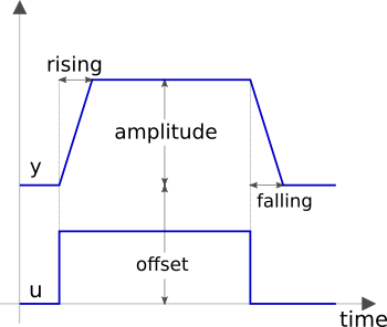
Block that represents a triggered trapezoid.
The block has a Boolean input and a Real
output signal and requires the parameters amplitude,
rising, falling and offset. The
output signal y represents a trapezoidal signal dependent on the
input signal u.
The behaviour is as follows: Assume the initial input to be
false. In this
case, the output will be offset. After a rising edge (i.e., the input
changes from false to true),
the output is rising during rising to the
sum of offset and amplitude. In contrast, after a falling
edge (i.e., the input changes from true to false), the output is falling
during falling to a value of offset.
Note, the case of edges before expiration of rising or falling is handled properly.
Extends from Modelica.Icons.ObsoleteModel (Icon for classes that are obsolete and will be removed in later versions).
Parameters
| Type | Name | Default | Description |
|---|---|---|---|
| Real | amplitude | Amplitude of trapezoid | |
| Real | rising | 0 | Rising duration of trapezoid [s] |
| Real | falling | rising | Falling duration of trapezoid [s] |
| Real | offset | 0 | Offset of output signal |
Connectors
| Type | Name | Description |
|---|---|---|
| input BooleanInput | u | Connector of Boolean input signal |
| output RealOutput | y | Connector of Real output signal |
Modelica definition
 Buildings.Obsolete.Controls.OBC.CDL.Logical.TrueHold
Block that holds a true signal for at least a requested duration
Information
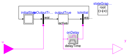
Block that holds a true input signal for at least a defined time period.
At initialization, the output y is equal to the input u.
If the input u becomes true, or is true
during intialization, a timer starts
and the Boolean output y stays true for the time
period provided by the parameter duration.
When this time is elapsed, the input is checked again. If
it is true, then the timer is restarted and the output remains
true for another duration seconds.
If the input u is false after
holdTime seconds, then the ouput is switched to false,
until the input becomes true again.
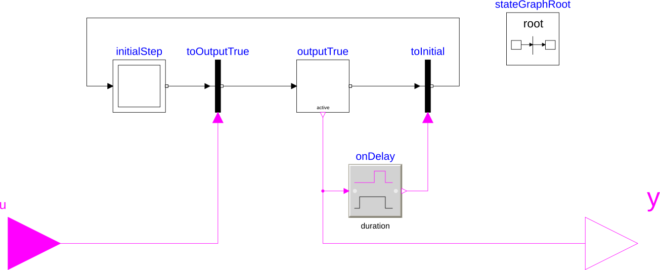
The figure below shows the state chart of the implementation. Note that the transition are done in zero time.
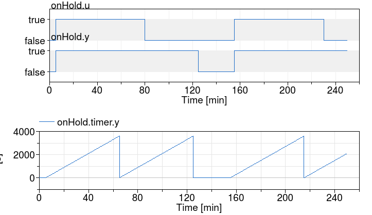
The figure below shows an example with a hold time of 3600 seconds and a pulse width period 9000 seconds that starts at t=200 seconds.
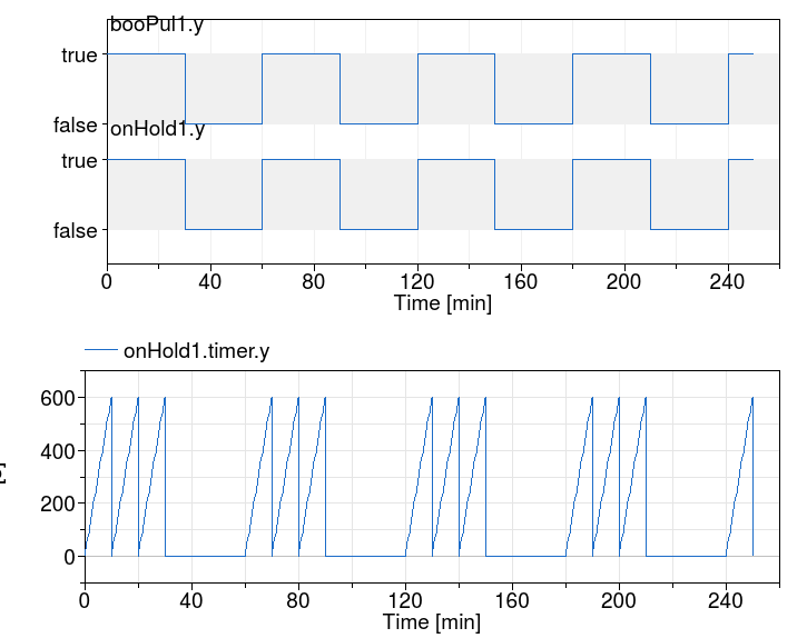
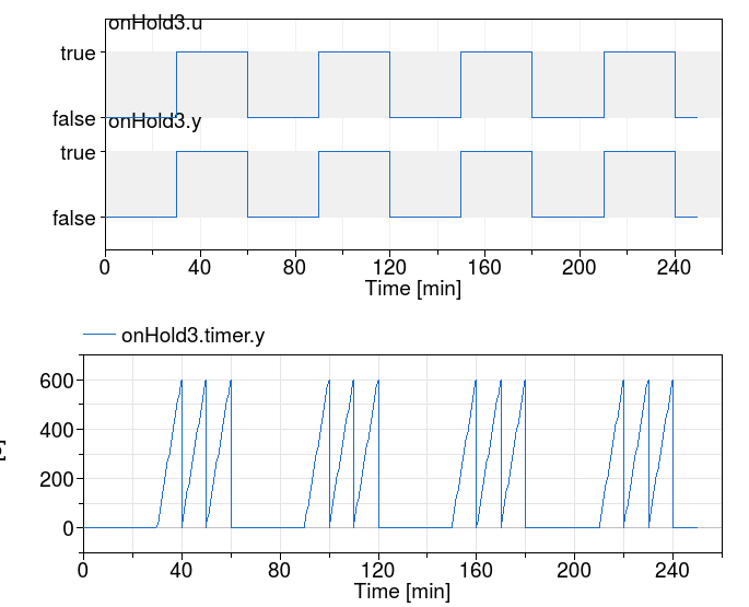
The figure below shows an example with a hold time of 60 seconds and a pulse width period 3600 seconds that starts at t=0 seconds.
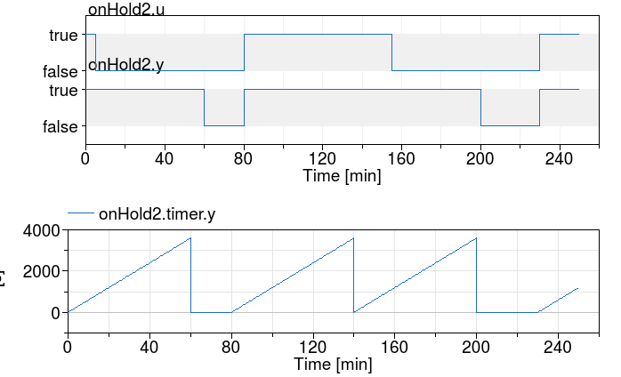
The next two figures show the same experiment, except that the input u
has been negated. The figure below has again a hold time of 3600 seconds
and a pulse width period 9000 seconds that starts at t=200 seconds.
The figure below has again a hold time of 60 seconds and a pulse width period 3600 seconds that starts at t=0 seconds.
Parameters
| Type | Name | Default | Description |
|---|---|---|---|
| Real | duration | Time duration of the true output signal hold [s] |
Connectors
| Type | Name | Description |
|---|---|---|
| input BooleanInput | u | Boolean input signal |
| output BooleanOutput | y | Boolean output signal |
Modelica definition
 Buildings.Obsolete.Controls.OBC.CDL.Logical.ZeroCrossing
Trigger zero crossing of input u
Information
Block that detects zero crossings.
The output y is true at the
time instant when the input u becomes
zero, provided the input enable is
true. At all other time instants,
the output y is false.
If the input u is zero at a time instant when
the enable
input changes its value, then the output y is false.
Note, that in the plot window of a Modelica simulator, the output of
this block is usually identically to false, because the output
may only be true at an event instant, but not during
continuous integration. In order to check that this component is
actually working as expected, one should connect its output to, e.g.,
component Buildings.Controls.OBC.CDL.Discrete.TriggeredSampler.
Extends from Modelica.Icons.ObsoleteModel (Icon for classes that are obsolete and will be removed in later versions).
Connectors
| Type | Name | Description |
|---|---|---|
| input RealInput | u | Connector of Real input signal |
| output BooleanOutput | y | Connector of Boolean output signal |
| input BooleanInput | enable | Zero input crossing is triggered if the enable input signal is true |