Package of control sequences for cooling plants
Information
This package contains control sequences for central cooling plants.
Extends from Modelica.Icons.VariantsPackage (Icon for package containing variants).
Package Content
| Name |
Description |
 ChilledWaterBypass ChilledWaterBypass
|
Controller for chilled water bypass valve |
 ChilledWaterPumpSpeed ChilledWaterPumpSpeed
|
Controller for two headered variable speed chilled water pumps |
 ChillerStage ChillerStage
|
Chiller staging controller for plants with two chillers of the same size |
 FlowControl FlowControl
|
This block controls the flow at the primary and secondary pumps |
 SelectMin SelectMin
|
Block that includes or excludes storage plant pressure signal for min |
 TankStatus TankStatus
|
Returns the tank status from its temperature sensors |
 Validation Validation
|
Collection of validation models |
Controller for chilled water bypass valve
Information
This model implements the chilled water loop bypass valve control logic as
follows:
When the plant is on, the PID controller controls the valve opening ratio to
reach the scaled mass flow rate setpoint.
The setpoint is mMin_flow multiplied by the number of chillers
that are on. mMin_flow is the minimum mass flow rate required by
one chiller.
This control sequence assumes that all the chillers are identical and the
cooling load is evenly split between all of the chillers that are on.
Parameters
| Type | Name | Default | Description |
|---|
| Integer | numChi | | Number of chillers |
| Real | mMin_flow | | Minimum mass flow rate of single chiller [kg/s] |
| SimpleController | controllerType | Buildings.Controls.OBC.CDL.T... | Type of controller |
| Real | k | 0.06 | Gain of controller |
| Real | Ti | 60 | Time constant of Integrator block [s] |
Connectors
| Type | Name | Description |
|---|
| input BooleanInput | chiOn[numChi] | On signals of the chillers |
| input RealInput | mFloChi | Mass flow rate through the chillers [kg/s] |
| output RealOutput | y | Bypass valve opening ratio |
Modelica definition
model ChilledWaterBypass
parameter Integer numChi(
min=1)
;
parameter Real mMin_flow(
final quantity="MassFlowRate",
final unit="kg/s")
;
parameter Buildings.Controls.OBC.CDL.Types.SimpleController controllerType=
Buildings.Controls.OBC.CDL.Types.SimpleController.PI
;
parameter Real k(min=0) = 0.06
;
parameter Real Ti(
final quantity="Time",
final unit="s",
final min=Buildings.Controls.OBC.CDL.Constants.small) = 60
;
Buildings.Controls.OBC.CDL.Interfaces.BooleanInput chiOn[numChi]
;
Buildings.Controls.OBC.CDL.Interfaces.RealInput mFloChi(
final unit="kg/s")
;
Buildings.Controls.OBC.CDL.Interfaces.RealOutput y
;
Buildings.Controls.OBC.CDL.Reals.PIDWithReset bypValCon(
controllerType=controllerType,
final k=k,
final Ti=Ti,
y_reset=0)
;
Buildings.Controls.OBC.CDL.Conversions.BooleanToInteger booToInt[numChi]
;
Buildings.Controls.OBC.CDL.Integers.GreaterThreshold intGreThr
;
Buildings.Controls.OBC.CDL.Integers.MultiSum numChiOn(nin=numChi)
;
Buildings.Controls.OBC.CDL.Conversions.IntegerToReal intToRea
;
Buildings.Controls.OBC.CDL.Reals.MultiplyByParameter mFloSetSca(
final k=1/numChi)
;
Buildings.Controls.OBC.CDL.Reals.MultiplyByParameter mFloBypSca(
final k=1/(numChi*mMin_flow))
;
equation
connect(chiOn, booToInt.u);
connect(booToInt.y, numChiOn.u);
connect(numChiOn.y, intGreThr.u);
connect(intGreThr.y, bypValCon.trigger);
connect(numChiOn.y, intToRea.u);
connect(bypValCon.y, y);
connect(intToRea.y, mFloSetSca.u);
connect(mFloSetSca.y, bypValCon.u_s);
connect(mFloChi, mFloBypSca.u);
connect(mFloBypSca.y, bypValCon.u_m);
end ChilledWaterBypass;
Controller for two headered variable speed chilled water pumps
Information
This model implements the control logic for variable speed pumps.
The staging of pumps is implemented through an instance of
Buildings.Applications.BaseClasses.Controls.VariableSpeedPumpStage.
The pump speed is controlled to maintain the pressure difference setpoint
through a PI controller.
The model inputs are the measured chilled water mass flow rate
masFloPum and the pressure difference dpMea at a
reference point from the demand side. The output y is a vector
of pump speeds.
The model currently only supports the control of two variable speed pumps.
Parameters
| Type | Name | Default | Description |
|---|
| Real | dpSetPoi | | Pressure difference setpoint [Pa] |
| Real | tWai | | Waiting time [s] |
| Real | m_flow_nominal | | Nominal mass flow rate of single chilled water pump [kg/s] |
| Real | minSpe | 0.05 | Minimum speed ratio required by chilled water pumps [1] |
| Real | criPoiFlo | 0.7*m_flow_nominal | Critcal point of flowrate for switching pump on or off [kg/s] |
| Real | deaBanFlo | 0.1*m_flow_nominal | Deadband for critical point of flowrate [kg/s] |
| Real | criPoiSpe | 0.5 | Critical point of speed signal for switching on or off |
| Real | deaBanSpe | 0.3 | Deadband for critical point of speed signal |
| Speed Controller |
| SimpleController | controllerType | Buildings.Controls.OBC.CDL.T... | Type of pump speed controller |
| Real | k | 1 | Gain of controller [1] |
| Real | Ti | 60 | Time constant of Integrator block [s] |
| Real | Td | 0.1 | Time constant of Derivative block [s] |
Connectors
| Type | Name | Description |
|---|
| input BooleanInput | on | On signal of the plant |
| input RealInput | masFloPum | Total mass flowrate of chilled water pumps [kg/s] |
| input RealInput | dpMea | Measured pressure difference [Pa] |
| output RealOutput | y[numPum] | Pump speed signal [1] |
Modelica definition
model ChilledWaterPumpSpeed
parameter Real dpSetPoi(
final unit="Pa",
final quantity="PressureDifference",
displayUnit="Pa")
;
parameter Real tWai(
final quantity="Time",
final unit="s")
;
parameter Real m_flow_nominal(
final unit="kg/s",
final quantity="MassFlowRate")
;
parameter Real minSpe(
final unit="1",
final min=0,
final max=1)=0.05
;
parameter Real criPoiFlo(
final unit="kg/s",
final quantity="MassFlowRate")=0.7*m_flow_nominal
;
parameter Real deaBanFlo(
final unit="kg/s",
final quantity="MassFlowRate")=0.1*m_flow_nominal
;
parameter Real criPoiSpe=0.5
;
parameter Real deaBanSpe=0.3
;
parameter Buildings.Controls.OBC.CDL.Types.SimpleController controllerType=
Buildings.Controls.OBC.CDL.Types.SimpleController.PI
;
parameter Real k(
final unit="1",
final min=0)=1
;
parameter Real Ti(
final quantity="Time",
final unit="s",
final min=Buildings.Controls.OBC.CDL.Constants.small) = 60
;
parameter Real Td(
final quantity="Time",
final unit="s",
final min=0) = 0.1
;
Buildings.Controls.OBC.CDL.Interfaces.BooleanInput on
;
Buildings.Controls.OBC.CDL.Interfaces.RealInput masFloPum(
final unit="kg/s")
;
Buildings.Controls.OBC.CDL.Interfaces.RealInput dpMea(
final unit="Pa")
;
Buildings.Controls.OBC.CDL.Interfaces.RealOutput y[numPum](
each final unit="1",
each final min=0,
each final max=1)
;
Buildings.Controls.OBC.CDL.Reals.Multiply pumSpe[numPum]
;
Buildings.Applications.BaseClasses.Controls.VariableSpeedPumpStage pumStaCon(
final tWai=tWai,
final m_flow_nominal=m_flow_nominal,
final minSpe=minSpe,
final criPoiFlo=criPoiFlo,
final deaBanFlo=deaBanFlo,
final criPoiSpe=criPoiSpe,
final deaBanSpe=deaBanSpe)
;
Buildings.Controls.OBC.CDL.Reals.PIDWithReset conPID(
final controllerType=controllerType,
final Ti=Ti,
final k=k,
final Td=Td)
;
Buildings.Controls.OBC.CDL.Reals.Sources.Constant dpSetSca(
final k=1)
;
Buildings.Controls.OBC.CDL.Reals.MultiplyByParameter gai(
final k=1/dpSetPoi)
;
Buildings.Controls.OBC.CDL.Reals.GreaterThreshold twoPum(
final t=1.5)
;
Buildings.Controls.OBC.CDL.Reals.MultiSum totPum(
final nin=numPum)
;
Buildings.Controls.OBC.CDL.Logical.Or orRes ;
protected
final parameter Integer numPum=2
;
equation
connect(pumStaCon.masFloPum,masFloPum);
connect(conPID.y,pumStaCon.speSig);
connect(pumStaCon.y,pumSpe.u1);
connect(conPID.y,pumSpe[1].u2);
connect(conPID.y,pumSpe[2].u2);
connect(dpSetSca.y,conPID.u_s);
connect(dpMea, gai.u);
connect(gai.y, conPID.u_m);
connect(pumStaCon.y, totPum.u);
connect(totPum.y, twoPum.u);
connect(pumSpe.y, y);
connect(on, pumStaCon.on);
connect(twoPum.y, orRes.u2);
connect(on, orRes.u1);
connect(orRes.y, conPID.trigger);
end ChilledWaterPumpSpeed;
Chiller staging controller for plants with two chillers of the same size
Information
This model implements the staging control logic as follows:
- When the plant enabling signal
on changes from
false to true, one chiller is enabled.
- When the total cooling load
QLoa exceeds 80 percent (adjustable)
of one chiller's nominal capacity QChi_nominal, a second
chiller is enabled.
- When the total cooling load
QLoa drops below 60 percent
(adjustable) of one chiller's nominal capacity QChi_nominal
(i.e. 30 percent of both chillers combined), or the plant enabling signal
on changes from true to false, the second
chiller is disabled.
- When the plant enabling signal
on changes from true
to false, the operating chillers will be disabled sequentially.
- Parameter
tWai assures a transitional time is kept between each
operation.
It is assumed that both chillers have the same capacity of
QChi_nominal.
Note: This model can be used for plants with two chillers with or without
waterside econimizer (WSE). For plants with WSE, extra control logic on top of
this model needs to be added.
 .
.
Parameters
| Type | Name | Default | Description |
|---|
| Real | cp_default | | Specific heat capacity of the fluid [J/(kg.K)] |
| Real | tWai | | Waiting time [s] |
| Real | QChi_nominal | | Nominal cooling capacity (negative) [W] |
| Real | staUpThr | -0.8*QChi_nominal | Stage up load threshold(from one to two chillers) [W] |
| Real | staDowThr | -0.6*QChi_nominal | Stage down load threshold(from two to one chiller) [W] |
Connectors
| Type | Name | Description |
|---|
| input BooleanInput | on | Enabling signal of the plant. True: chiller should be enabled |
| input RealInput | TChiWatRet | Chilled water return temperature |
| input RealInput | TChiWatSup | Chilled water supply temperature |
| input RealInput | mFloChiWat | Chilled water mass flow rate |
| output BooleanOutput | y[2] | On/off signal for the chillers - false: off; true: on |
Modelica definition
model ChillerStage
parameter Real cp_default(
final quantity="SpecificHeatCapacity",
final unit="J/(kg.K)")
;
parameter Real tWai(
final unit="s",
final quantity="Time")
;
parameter Real QChi_nominal(
final max=0,
final quantity="Power",
final unit="W")
;
parameter Real staUpThr(
final min=0,
final quantity="Power",
final unit="W") = -0.8*QChi_nominal
;
parameter Real staDowThr(
final min=0,
final quantity="Power",
final unit="W") = -0.6*QChi_nominal
;
inner Modelica.StateGraph.StateGraphRoot stateGraphRoot
;
Buildings.Controls.OBC.CDL.Interfaces.BooleanInput on
;
Buildings.Controls.OBC.CDL.Interfaces.RealInput TChiWatRet
;
Buildings.Controls.OBC.CDL.Interfaces.RealInput TChiWatSup
;
Buildings.Controls.OBC.CDL.Interfaces.RealInput mFloChiWat
;
Buildings.Controls.OBC.CDL.Interfaces.BooleanOutput y[2]
;
Modelica.StateGraph.InitialStep off(nIn=1, nOut=1)
;
Modelica.StateGraph.StepWithSignal oneOn(
nOut=2,
nIn=2)
;
Modelica.StateGraph.StepWithSignal twoOn(nOut=1, nIn=1)
;
Modelica.StateGraph.TransitionWithSignal offToOne(
enableTimer=true,
waitTime=tWai)
;
Modelica.StateGraph.TransitionWithSignal oneToTwo(
enableTimer=true,
waitTime=tWai)
;
Modelica.StateGraph.TransitionWithSignal twoToOne(
enableTimer=true,
waitTime=tWai) ;
Modelica.StateGraph.TransitionWithSignal oneToOff(
enableTimer=true,
waitTime=tWai)
;
Buildings.Controls.OBC.CDL.Reals.Hysteresis thrOneToTwo(
final uLow=-staDowThr/QChi_nominal,
final uHigh=-staUpThr/QChi_nominal)
;
Buildings.Controls.OBC.CDL.Logical.Not thrTwoToOne
;
Buildings.Controls.OBC.CDL.Reals.Subtract dT
;
Buildings.Controls.OBC.CDL.Reals.Multiply pro
;
Buildings.Controls.OBC.CDL.Reals.MultiplyByParameter plr(
final k=cp_default/QChi_nominal)
;
Buildings.Controls.OBC.CDL.Logical.Or Or
;
Buildings.Controls.OBC.CDL.Logical.Not notOn ;
Buildings.Controls.OBC.CDL.Logical.Or TwoToOne
;
equation
connect(off.outPort[1],offToOne.inPort);
connect(oneToTwo.outPort,twoOn.inPort[1]);
connect(twoToOne.outPort,oneOn.inPort[2]);
connect(oneOn.outPort[2],oneToOff.inPort);
connect(oneOn.outPort[1],oneToTwo.inPort);
connect(oneToTwo.condition,thrOneToTwo.y);
connect(dT.y,pro.u1);
connect(plr.u, pro.y);
connect(plr.y, thrOneToTwo.u);
connect(pro.u2,mFloChiWat);
connect(oneToTwo.condition, thrTwoToOne.u);
connect(oneOn.active, Or.u1);
connect(twoOn.active, Or.u2);
connect(Or.y, y[1]);
connect(twoOn.active, y[2]);
connect(on, notOn.u);
connect(twoOn.outPort[1],twoToOne.inPort);
connect(offToOne.outPort,oneOn.inPort[1]);
connect(oneToOff.outPort,off.inPort[1]);
connect(on, offToOne.condition);
connect(thrTwoToOne.y, TwoToOne.u2);
connect(notOn.y, TwoToOne.u1);
connect(TwoToOne.y, twoToOne.condition);
connect(notOn.y, oneToOff.condition);
connect(TChiWatSup, dT.u1);
connect(TChiWatRet, dT.u2);
end ChillerStage;
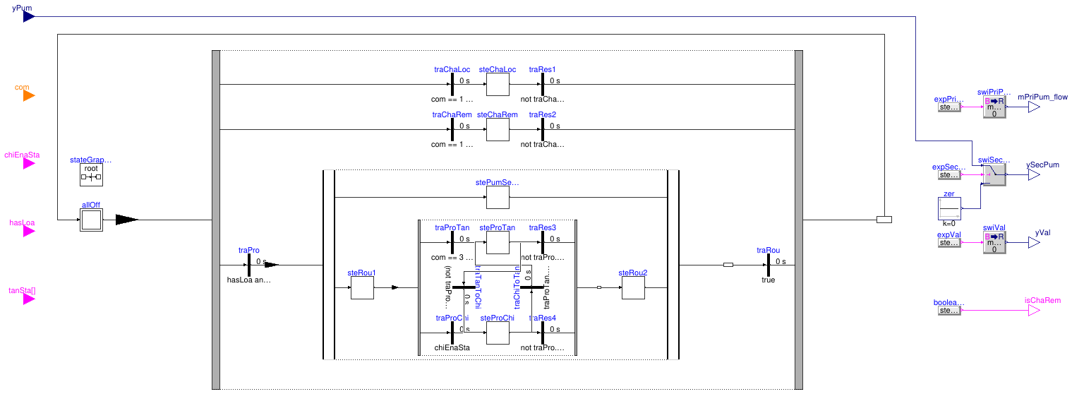
This block controls the flow at the primary and secondary pumps
Information
This block implements a state graph to control the flows of the storage plant.
It receives two tank status Boolean signals indicating that the tank
is charged or empty. These two signals can be both false indicating an
in-between state. The block can receive one of the following commands:
-
Charge tank,
-
No command, and
-
Discharge tank.
The command to tank may be disregarded. For example, if the
tank is receiving a discharge command but it is already empty, it will not
discharge which would let warm return water directly into the supply side.
The system transitions among the following states:
| Step |
Description |
Transition in |
Transition out |
All Off
(Initial Step) |
All off. This is the initial step. |
- |
- |
| Local Charging |
Charge the tank with the local chiller. |
"Charge tank" command
AND tank is not charged yet
AND chiller is enabled.
This transition takes priority
over the one below.1 |
The in-transition condition becomes false. |
| Remote Charging |
Charge the tank with the remote chiller. |
Same as above except that
the chiller is not enabled. |
The in-transition condition becomes false. |
| Secondary Pump On |
Turn on the secondary pump.
This step is in parallel with the two below.2 |
The district has load AND
the additional conditions of
either step below become true. |
Both steps below are no longer active (implicit). |
| Tank Producing |
The tank produces CHW to the district.
This step is in parallel with "secondary pump on". |
The district has load AND
"Discharge tank" command AND
tank not empty.
This transition takes priority
over the one below. |
To "chiller producing": The in-transition condition becomes false AND
The chiller is enabled.
This transition takes priority over the one below. |
To initial step: No load OR the in-transition conditions
of "tank producing" and "chiller producing" are both false
(i.e. neither tank or chiller is available). |
| Chiller Producing |
The chiller produces CHW to the district.
This step is in parallel with "secondary pump on". |
The district has load AND
the chiller is enabled. |
To "tank producing": The condition for in-transition of
"tank producing" becomes true.
This transition takes priority over the one below. |
To initial step: No load OR the in-transition conditions
of "tank producing" and "chiller producing" are both false. |
Notes:
-
Out-transitions from the same step have priorities. When the conditions of
more than one of them become true, the transition connected by a connector
with the lowest index in the array fires.
For example, even when the in-transition condition of "chiller producing"
becomes true, as long as the in-transition condition of "tank producing"
is also true, the latter fires because of priority.
-
Steps that are in parallel are and must be active at the same time.
When "secondary pump on" is active, either "tank producing"
or "chiller producing" is also active.
Parameters
| Type | Name | Default | Description |
|---|
| Nominal values |
| Real | mChi_flow_nominal | | Nominal mass flow rate of the chiller loop [kg/s] |
| Real | mTan_flow_nominal | | Nominal mass flow rate of the tank branch [kg/s] |
Connectors
| Type | Name | Description |
|---|
| input IntegerInput | com | Command: 1 = charge tank, 2 = no command, 3 = discharge tank |
| input BooleanInput | chiEnaSta | Chiller enable status, true if chiller is enabled |
| input BooleanInput | hasLoa | Set to true if there is a load |
| input RealInput | yPum | Normalized speed signal for the secondary pump [1] |
| input BooleanInput | tanSta[2] | Tank status - 1: is empty; 2: is charged; can be both false |
| output BooleanOutput | isChaRem | Is operated for remote charging |
| output RealOutput | yVal | Valve normalized mass flow rate |
| output RealOutput | mPriPum_flow | Primary pump mass flow rate [kg/s] |
| output RealOutput | ySecPum | Secondary pump normalized speed [1] |
Modelica definition
block FlowControl
parameter Real mChi_flow_nominal(
final quantity="MassFlowRate",
final unit="kg/s")
;
parameter Real mTan_flow_nominal(
final quantity="MassFlowRate",
final unit="kg/s")
;
Buildings.Controls.OBC.CDL.Interfaces.IntegerInput com
;
Buildings.Controls.OBC.CDL.Interfaces.BooleanInput chiEnaSta
;
Buildings.Controls.OBC.CDL.Interfaces.BooleanInput hasLoa
;
Buildings.Controls.OBC.CDL.Interfaces.RealInput yPum(
final unit="1")
;
Buildings.Controls.OBC.CDL.Interfaces.BooleanInput tanSta[2]
;
Buildings.Controls.OBC.CDL.Interfaces.BooleanOutput isChaRem
;
Buildings.Controls.OBC.CDL.Interfaces.RealOutput yVal
;
Buildings.Controls.OBC.CDL.Interfaces.RealOutput mPriPum_flow(
final unit="kg/s")
;
Buildings.Controls.OBC.CDL.Interfaces.RealOutput ySecPum(
final unit="1")
;
inner Modelica.StateGraph.StateGraphRoot stateGraphRoot ;
Modelica.StateGraph.InitialStep allOff(nOut=1, nIn=1) ;
Modelica.StateGraph.Transition traChaLoc(
condition=com == 1
and (
not tanSta[2])
and chiEnaSta)
;
Modelica.StateGraph.Step steChaLoc(nIn=1, nOut=1)
;
Modelica.StateGraph.Transition traRes1(
condition=
not traChaLoc.condition)
;
Modelica.StateGraph.Transition traChaRem(
condition=com == 1
and (
not tanSta[2])
and not chiEnaSta)
;
Modelica.StateGraph.Step steChaRem(
nIn=1, nOut=1)
;
Modelica.StateGraph.Transition traRes2(
condition=
not traChaRem.condition)
;
Modelica.StateGraph.Transition traProChi(
condition=chiEnaSta)
;
Modelica.StateGraph.Step steProChi(
nIn=2, nOut=2)
;
Modelica.StateGraph.Transition traRes4(
condition=
not traPro.condition)
;
Modelica.StateGraph.Transition traProTan(
condition=com == 3
and (
not tanSta[1]))
;
Modelica.StateGraph.Step steProTan(
nIn=2, nOut=2)
;
Modelica.StateGraph.Transition traRes3(
condition=
not traPro.condition)
;
Modelica.Blocks.Sources.BooleanExpression expPriPumFlo(
y=steChaLoc.active
or steProChi.active)
;
Buildings.Controls.OBC.CDL.Conversions.BooleanToReal swiPriPum(
realTrue=mChi_flow_nominal,
realFalse=0)
;
Modelica.Blocks.Sources.BooleanExpression expSecPum(
y=stePumSecOn.active)
;
Modelica.Blocks.Sources.BooleanExpression expVal(
y=steChaRem.active)
;
Modelica.StateGraph.Alternative alt(
nBranches=3)
;
Buildings.Controls.OBC.CDL.Reals.Switch swiSecPum
;
Buildings.Controls.OBC.CDL.Reals.Sources.Constant zer(
final k=0) ;
Buildings.Controls.OBC.CDL.Conversions.BooleanToReal swiVal(
realTrue=mTan_flow_nominal,
realFalse=0)
;
Modelica.StateGraph.Step stePumSecOn(nOut=1, nIn=1)
;
Modelica.StateGraph.Transition traPro(
condition=hasLoa
and (traProTan.condition
or traProChi.condition))
;
Modelica.StateGraph.Parallel parallel(
nBranches=2)
;
Modelica.StateGraph.Transition traTanToChi(
condition=(
not traProTan.condition)
and traProChi.condition)
;
Modelica.StateGraph.Alternative altTanCha1(nBranches=2)
;
Modelica.StateGraph.Step steRou1(nIn=1, nOut=1)
;
Modelica.StateGraph.Step steRou2(nIn=1, nOut=1)
;
Modelica.StateGraph.Transition traRou(
final condition=true)
;
Modelica.StateGraph.Transition traChiToTan(
condition=traProTan.condition)
;
Modelica.Blocks.Sources.BooleanExpression booleanExpression(
y=steChaRem.active);
equation
connect(traChaLoc.outPort,steChaLoc. inPort[1]);
connect(steChaLoc.outPort[1], traRes1.inPort);
connect(traChaRem.outPort,steChaRem. inPort[1]);
connect(steChaRem.outPort[1], traRes2.inPort);
connect(traProChi.outPort,steProChi. inPort[1]);
connect(traProTan.outPort,steProTan. inPort[1]);
connect(expPriPumFlo.y, swiPriPum.u);
connect(alt.inPort, allOff.outPort[1]);
connect(alt.outPort, allOff.inPort[1]);
connect(mPriPum_flow, swiPriPum.y);
connect(expSecPum.y, swiSecPum.u2);
connect(swiSecPum.u1, yPum);
connect(ySecPum, swiSecPum.y);
connect(zer.y, swiSecPum.u3);
connect(swiVal.u, expVal.y);
connect(swiVal.y, yVal);
connect(traPro.outPort, parallel.inPort);
connect(parallel.split[1], stePumSecOn.inPort[1]);
connect(stePumSecOn.outPort[1], parallel.join[1]);
connect(traTanToChi.outPort, steProChi.inPort[2]);
connect(traProTan.inPort, altTanCha1.split[1]);
connect(traRes3.outPort, altTanCha1.join[1]);
connect(traProChi.inPort, altTanCha1.split[2]);
connect(traRes4.outPort, altTanCha1.join[2]);
connect(steRou1.outPort[1], altTanCha1.inPort);
connect(altTanCha1.outPort,steRou2. inPort[1]);
connect(steRou1.inPort[1], parallel.split[2]);
connect(steRou2.outPort[1], parallel.join[2]);
connect(parallel.outPort, traRou.inPort);
connect(traChaLoc.inPort, alt.split[1]);
connect(traChaRem.inPort, alt.split[2]);
connect(traRes1.outPort, alt.join[1]);
connect(traRes2.outPort, alt.join[2]);
connect(traPro.inPort, alt.split[3]);
connect(traRou.outPort, alt.join[3]);
connect(booleanExpression.y, isChaRem);
connect(traChiToTan.outPort, steProTan.inPort[2]);
connect(steProChi.outPort[1], traChiToTan.inPort);
connect(steProChi.outPort[2], traRes4.inPort);
connect(steProTan.outPort[1], traTanToChi.inPort);
connect(steProTan.outPort[2], traRes3.inPort);
end FlowControl;
Block that includes or excludes storage plant pressure signal for min
Information
This block finds the minimum value from pressure head signals.
The signal from the storage plant is included
only when the plant is in remote charging mode.
Connectors
| Type | Name | Description |
|---|
| input RealInput | dpUse[nin] | Connector of Real input signals |
| input RealInput | dpStoPla | Connector of Real input signals |
| input BooleanInput | isChaRem | The storage plant is in remote charging mode |
| output RealOutput | y | |
Modelica definition
Returns the tank status from its temperature sensors
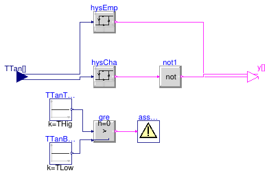
Information
This model outputs tank status signals using the temperatures
at the CHW tank top and the tank bottom as input.
The status has two separate boolean signals indicating whether the tank is
charged or empty (of cooling). The two output signals can be both false,
indicating an in-between state, but they can never both be true.
Parameters
| Type | Name | Default | Description |
|---|
| Real | THig | | Higher threshold to consider the tank empty [K] |
| Real | TLow | | Lower threshold to consider the tank full [K] |
| Real | dTHys | 0.5 | Deadband for hysteresis [K] |
Connectors
| Type | Name | Description |
|---|
| input RealInput | TTan[2] | Temperatures at the tank 1: top; and 2: bottom [K] |
| output BooleanOutput | y[2] | Tank status - y[1]=true is empty; y[2] = true is charged; both false means partially charged |
Modelica definition
block TankStatus
parameter Real THig(
final quantity="ThermodynamicTemperature",
final unit="K",
displayUnit="degC")
;
parameter Real TLow(
final quantity="ThermodynamicTemperature",
final unit="K",
displayUnit="degC")
;
parameter Real dTHys(
min=0.1,
final unit="K",
final quantity="TemperatureDifference") = 0.5
;
Buildings.Controls.OBC.CDL.Interfaces.RealInput TTan[2](
each final quantity="Temperature",
each final unit="K",
each displayUnit="degC") ;
Buildings.Controls.OBC.CDL.Interfaces.BooleanOutput y[2]
;
Buildings.Controls.OBC.CDL.Reals.Hysteresis hysCha(
final uLow=TLow,
final uHigh=TLow + dTHys) ;
Buildings.Controls.OBC.CDL.Reals.Hysteresis hysEmp(
final uHigh=THig,
final uLow=THig - dTHys) ;
Buildings.Controls.OBC.CDL.Logical.Not not1 ;
Buildings.Controls.OBC.CDL.Reals.Sources.Constant TTanTopChe(
final k(
final unit="K", displayUnit="degC") = THig)
;
Buildings.Controls.OBC.CDL.Reals.Sources.Constant TTanBotChe(
final k(
final unit="K", displayUnit="degC") = TLow)
;
Buildings.Controls.OBC.CDL.Reals.Greater gre
;
Buildings.Controls.OBC.CDL.Utilities.Assert assMes(
message = "THig must be greater than TLow.")
;
equation
connect(hysCha.y, not1.u);
connect(TTan[1],hysCha. u);
connect(TTan[2],hysEmp. u);
connect(TTanTopChe.y, gre.u1);
connect(TTanBotChe.y, gre.u2);
connect(gre.y, assMes.u);
connect(hysEmp.y, y[1]);
connect(not1.y, y[2]);
end TankStatus;
 Buildings.DHC.Plants.Cooling.Controls.ChilledWaterBypass
 Buildings.DHC.Plants.Cooling.Controls.ChilledWaterPumpSpeed
 Buildings.DHC.Plants.Cooling.Controls.ChillerStage
 Buildings.DHC.Plants.Cooling.Controls.FlowControl
 Buildings.DHC.Plants.Cooling.Controls.SelectMin
 Buildings.DHC.Plants.Cooling.Controls.TankStatus