Buildings.DHC.ETS.Heating
This package contains models for energy transfer stations used in district heating systems
Information
This package contains models for energy transfer stations used in district heating systems.
Extends from Modelica.Icons.VariantsPackage (Icon for package containing variants).
Package Content
| Name | Description |
|---|---|
| Direct heating ETS model for district energy systems with in-building pumping and deltaT control | |
| Indirect heating energy transfer station for district energy systems | |
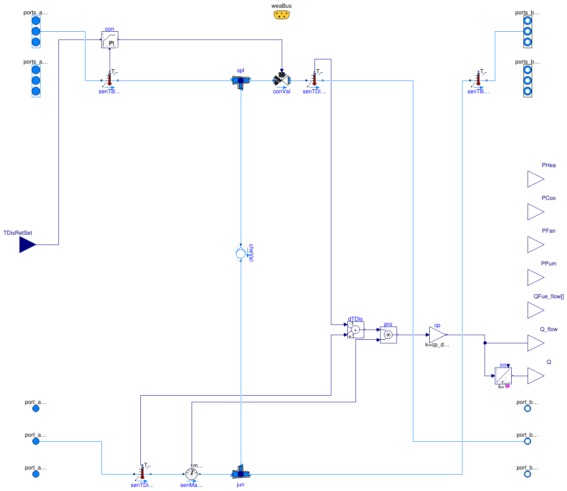
 Buildings.DHC.ETS.Heating.Direct
Direct heating ETS model for district energy systems with in-building
pumping and deltaT control
Information
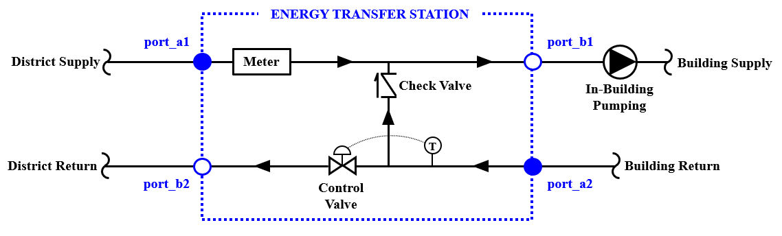
Direct heating energy transfer station (ETS) model with in-building pumping and deltaT control. The design is based on a typical district heating ETS described in ASHRAE's District Heating Guide. As shown in the figure below, the district and building piping are hydronically coupled. The control valve ensures that the return temperature to the district heating network is at or below the maximum specified value. This configuration naturally results in a fluctuating building supply tempearture.
Reference
American Society of Heating, Refrigeration and Air-Conditioning Engineers. (2013). Chapter 5: Consumer Interconnection. In District Heating Guide.
Extends from Buildings.DHC.ETS.BaseClasses.PartialDirect (Partial direct ETS model for district energy systems with in-building pumping and deltaT control).
Parameters
| Type | Name | Default | Description |
|---|---|---|---|
| replaceable package MediumSer | Water | Service side medium | |
| replaceable package MediumSerHea_a | Water | Service side medium at heating inlet | |
| replaceable package MediumBui | Water | Building side medium | |
| Generic | fue[nFue] | Fuel type | |
| Configuration | |||
| DistrictSystemType | typ | Buildings.DHC.Types.District... | Type of district system |
| Boolean | have_heaWat | true | Set to true if the ETS supplies heating water |
| Boolean | have_chiWat | false | Set to true if the ETS supplies chilled water |
| Nominal condition | |||
| HeatFlowRate | QHeaWat_flow_nominal | 0 | Nominal capacity of heating system (>=0) [W] |
| HeatFlowRate | QHotWat_flow_nominal | 0 | Nominal capacity of hot water production system (>=0) [W] |
| HeatFlowRate | QChiWat_flow_nominal | 0 | Nominal capacity of cooling system (<=0) [W] |
| MassFlowRate | mBui_flow_nominal | Nominal mass flow rate of building side [kg/s] | |
| PressureDifference | dpConVal_nominal | 50 | Nominal pressure drop in the control valve [Pa] |
| PressureDifference | dpCheVal_nominal | 6000 | Nominal pressure drop in the check valve [Pa] |
| PID controller | |||
| SimpleController | controllerType | Modelica.Blocks.Types.Simple... | Type of controller |
| Real | k | 0.1 | Gain of controller [1] |
| Time | Ti | 60 | Time constant of integrator block [s] |
| Time | Td | 0.1 | Time constant of derivative block [s] |
| Real | yMax | 1 | Upper limit of output |
| Real | yMin | 0 | Lower limit of output |
| Assumptions | |||
| Boolean | allowFlowReversalSer | false | Set to true to allow flow reversal on service side |
| Boolean | allowFlowReversalBui | false | Set to true to allow flow reversal on building side |
| Advanced | |||
| Dynamics | energyDynamics | Modelica.Fluid.Types.Dynamic... | Type of energy balance: dynamic (3 initialization options) or steady state |
| Real | bandwidth | 0.2 | Bandwidth around reference signal for on/off controller |
Connectors
| Type | Name | Description |
|---|---|---|
| FluidPorts_a | ports_aHeaWat[nPorts_aHeaWat] | Fluid connectors for heating water return (from building) |
| FluidPorts_b | ports_bHeaWat[nPorts_bHeaWat] | Fluid connectors for heating water supply (to building) |
| FluidPorts_a | ports_aChiWat[nPorts_aChiWat] | Fluid connectors for chilled water return (from building) |
| FluidPorts_b | ports_bChiWat[nPorts_bChiWat] | Fluid connectors for chilled water supply (to building) |
| FluidPort_a | port_aSerAmb | Fluid connector for ambient water service supply line |
| FluidPort_b | port_bSerAmb | Fluid connector for ambient water service return line |
| FluidPort_a | port_aSerHea | Fluid connector for heating service supply line |
| FluidPort_b | port_bSerHea | Fluid connector for heating service return line |
| FluidPort_a | port_aSerCoo | Fluid connector for cooling service supply line |
| FluidPort_b | port_bSerCoo | Fluid connector for cooling service return line |
| output RealOutput | PHea | Power drawn by heating system [W] |
| output RealOutput | PCoo | Power drawn by cooling system [W] |
| output RealOutput | PFan | Power drawn by fan motors [W] |
| output RealOutput | PPum | Power drawn by pump motors [W] |
| output RealOutput | QFue_flow[nFue] | Fuel energy input rate [W] |
| Bus | weaBus | Weather data bus |
| input RealInput | TDisRetSet | Setpoint for the district return temperature (min for cooling, max for heating) [K] |
| output RealOutput | Q_flow | Measured heating demand at the ETS [W] |
| output RealOutput | Q | Measured energy consumption at the ETS [J] |
Modelica definition
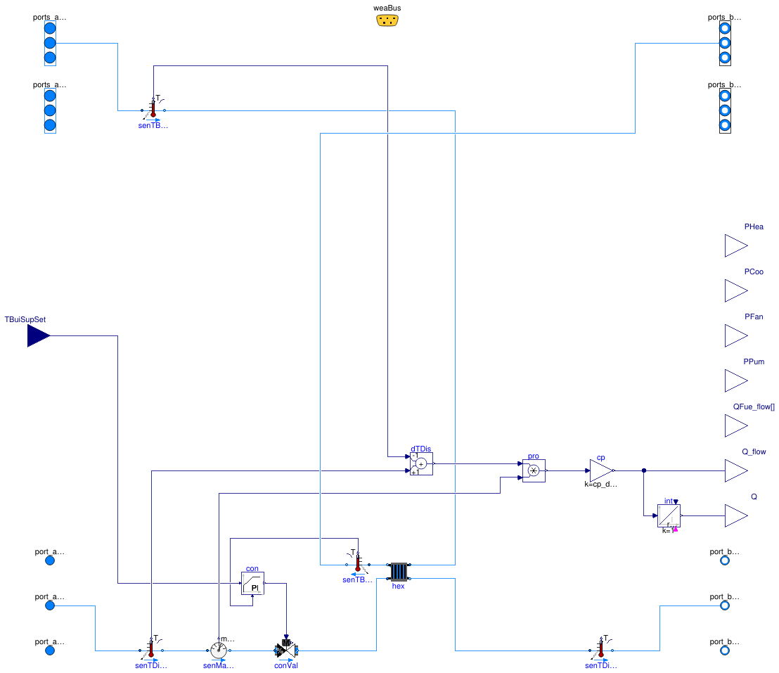
 Buildings.DHC.ETS.Heating.Indirect
Indirect heating energy transfer station for district energy systems
Information
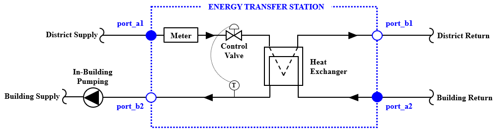
Indirect heating energy transfer station (ETS) model that controls the building chilled water supply temperature by modulating a primary control valve on the district supply side. The design is based on a typical district heating ETS described in ASHRAE's District Heating Guide. As shown in the figure below, the building pumping design (constant/variable) is specified on the building side and not within the ETS.
Reference
American Society of Heating, Refrigeration and Air-Conditioning Engineers. (2013). Chapter 5: Consumer Interconnection. In District Heating Guide.
Extends from Buildings.DHC.ETS.BaseClasses.PartialIndirect (Partial indirect energy transfer station for district energy systems).
Parameters
| Type | Name | Default | Description |
|---|---|---|---|
| replaceable package MediumSer | Water | Service side medium | |
| replaceable package MediumSerHea_a | Water | Service side medium at heating inlet | |
| replaceable package MediumBui | Water | Building side medium | |
| Generic | fue[nFue] | Fuel type | |
| Configuration | |||
| DistrictSystemType | typ | Buildings.DHC.Types.District... | Type of district system |
| Boolean | have_heaWat | true | Set to true if the ETS supplies heating water |
| Boolean | have_chiWat | false | Set to true if the ETS supplies chilled water |
| Nominal condition | |||
| HeatFlowRate | QHeaWat_flow_nominal | Q_flow_nominal | Nominal capacity of heating system (>=0) [W] |
| HeatFlowRate | QHotWat_flow_nominal | 0 | Nominal capacity of hot water production system (>=0) [W] |
| HeatFlowRate | QChiWat_flow_nominal | 0 | Nominal capacity of cooling system (<=0) [W] |
| MassFlowRate | mDis_flow_nominal | Nominal mass flow rate of district side [kg/s] | |
| MassFlowRate | mBui_flow_nominal | Nominal mass flow rate of building side [kg/s] | |
| PressureDifference | dpConVal_nominal | 6000 | Nominal pressure drop of fully open control valve [Pa] |
| Heat exchanger | |||
| PressureDifference | dp1_nominal | Nominal pressure difference on primary side [Pa] | |
| PressureDifference | dp2_nominal | Nominal pressure difference on secondary side [Pa] | |
| Boolean | use_Q_flow_nominal | true | Set to true to specify Q_flow_nominal and temeratures, or to false to specify effectiveness |
| Temperature | T_a1_nominal | Nominal temperature at port a1 (district supply) [K] | |
| Temperature | T_a2_nominal | Nominal temperature at port a2 (building return) [K] | |
| Efficiency | eta | 0.8 | Constant effectiveness [1] |
| PID controller | |||
| SimpleController | controllerType | Modelica.Blocks.Types.Simple... | Type of controller |
| Real | k | 1 | Gain of controller [1] |
| Time | Ti | 120 | Time constant of integrator block [s] |
| Time | Td | 0.1 | Time constant of derivative block [s] |
| Real | yMax | 1 | Upper limit of output |
| Real | yMin | 0.01 | Lower limit of output |
| Assumptions | |||
| Boolean | allowFlowReversalSer | false | Set to true to allow flow reversal on service side |
| Boolean | allowFlowReversalBui | false | Set to true to allow flow reversal on building side |
Connectors
| Type | Name | Description |
|---|---|---|
| FluidPorts_a | ports_aHeaWat[nPorts_aHeaWat] | Fluid connectors for heating water return (from building) |
| FluidPorts_b | ports_bHeaWat[nPorts_bHeaWat] | Fluid connectors for heating water supply (to building) |
| FluidPorts_a | ports_aChiWat[nPorts_aChiWat] | Fluid connectors for chilled water return (from building) |
| FluidPorts_b | ports_bChiWat[nPorts_bChiWat] | Fluid connectors for chilled water supply (to building) |
| FluidPort_a | port_aSerAmb | Fluid connector for ambient water service supply line |
| FluidPort_b | port_bSerAmb | Fluid connector for ambient water service return line |
| FluidPort_a | port_aSerHea | Fluid connector for heating service supply line |
| FluidPort_b | port_bSerHea | Fluid connector for heating service return line |
| FluidPort_a | port_aSerCoo | Fluid connector for cooling service supply line |
| FluidPort_b | port_bSerCoo | Fluid connector for cooling service return line |
| output RealOutput | PHea | Power drawn by heating system [W] |
| output RealOutput | PCoo | Power drawn by cooling system [W] |
| output RealOutput | PFan | Power drawn by fan motors [W] |
| output RealOutput | PPum | Power drawn by pump motors [W] |
| output RealOutput | QFue_flow[nFue] | Fuel energy input rate [W] |
| Bus | weaBus | Weather data bus |
| input RealInput | TBuiSupSet | Setpoint temperature for building supply |
| output RealOutput | Q_flow | Measured heating demand at the ETS [W] |
| output RealOutput | Q | Measured energy consumption at the ETS [J] |