Package of subsequences for dual-duct terminal unit using mixing control with discharge flow sensor
Information
This package contains subsequences for dual-duct terminal unit using mixing control with discharge flow sensor.
They are created according to Section 5.13 of ASHRAE Guideline 36, May 2020.
Package Content
| Name |
Description |
 ActiveAirFlow ActiveAirFlow
|
Output the active airflow setpoint for dual-duct terminal unit using mixing control with discharge flow sensor |
 Alarms Alarms
|
Generate alarms of dual-duct terminal unit using mixing control with discharge flow sensor |
 Dampers Dampers
|
Output signals for controlling dampers of dual-duct terminal unit using mixing control with discharge flow sensor |
 Overrides Overrides
|
Software switches to override setpoints |
 SystemRequests SystemRequests
|
Output system requests for dual-duct unit using mixing control with discharge flow sensor |
 Validation Validation
|
Collection of validation models |
Output the active airflow setpoint for dual-duct terminal unit using mixing control with discharge flow sensor
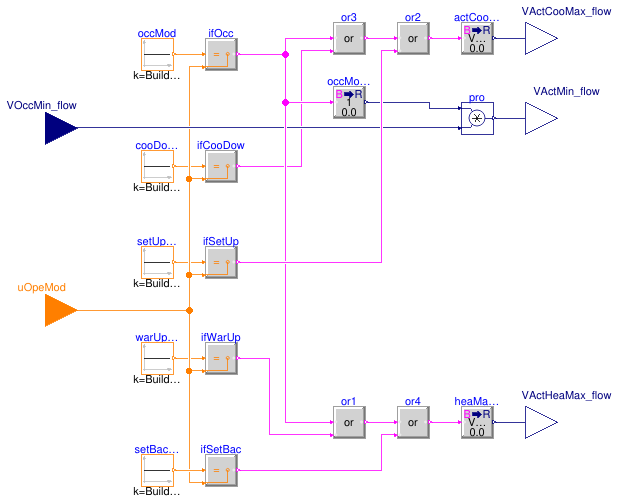
Information
This sequence sets the active cooling and heating maximum and the active minimum setpoints
for dual-duct terminal unit using mixing control with discharge flow sensor.
The implementation is according to the Section 5.13.4 of ASHRAE Guideline 36, May 2020.
The setpoints shall vary depending on the mode of the zone group.
| Setpoint | Occupied | Cooldown |
Setup | Warm-up | Setback | Unoccupied |
|---|
Cooling maximum (VActCooMax_flow) | VCooMax_flow |
VCooMax_flow | VCooMax_flow |
0 | 0 | 0 |
Minimum (VActMin_flow) | VOccMin_flow | 0 |
0 | 0 | 0 | 0 |
Heating maximum (VActHeaMax_flow) | VHeaMax_flow |
0 | 0 | VHeaMax_flow | VHeaMax_flow |
0 |
Parameters
| Type | Name | Default | Description |
|---|
| Real | VCooMax_flow | | Design zone cooling maximum airflow rate [m3/s] |
| Real | VHeaMax_flow | | Design zone heating maximum airflow rate [m3/s] |
Connectors
| Type | Name | Description |
|---|
| input RealInput | VOccMin_flow | Occupied minimum airflow setpoint [m3/s] |
| input IntegerInput | uOpeMod | Zone operation mode |
| output RealOutput | VActCooMax_flow | Active cooling maximum airflow setpoint [m3/s] |
| output RealOutput | VActMin_flow | Active minimum airflow setpoint [m3/s] |
| output RealOutput | VActHeaMax_flow | Active heating maximum airflow setpoint [m3/s] |
Modelica definition
block ActiveAirFlow
parameter Real VCooMax_flow(
final quantity="VolumeFlowRate",
final unit="m3/s")
;
parameter Real VHeaMax_flow(
final quantity="VolumeFlowRate",
final unit="m3/s")
;
Buildings.Controls.OBC.CDL.Interfaces.RealInput VOccMin_flow(
final unit="m3/s",
final quantity="VolumeFlowRate")
;
Buildings.Controls.OBC.CDL.Interfaces.IntegerInput uOpeMod
;
Buildings.Controls.OBC.CDL.Interfaces.RealOutput VActCooMax_flow(
final min=0,
final unit="m3/s",
final quantity="VolumeFlowRate")
;
Buildings.Controls.OBC.CDL.Interfaces.RealOutput VActMin_flow(
final min=0,
final unit="m3/s",
final quantity="VolumeFlowRate")
;
Buildings.Controls.OBC.CDL.Interfaces.RealOutput VActHeaMax_flow(
final min=0,
final unit="m3/s",
final quantity="VolumeFlowRate")
;
protected
Buildings.Controls.OBC.CDL.Integers.Sources.Constant occMod(
final k=Buildings.Controls.OBC.ASHRAE.G36.Types.OperationModes.occupied)
;
Buildings.Controls.OBC.CDL.Integers.Sources.Constant cooDowMod(
final k=Buildings.Controls.OBC.ASHRAE.G36.Types.OperationModes.coolDown)
;
Buildings.Controls.OBC.CDL.Integers.Sources.Constant setUpMod(
final k=Buildings.Controls.OBC.ASHRAE.G36.Types.OperationModes.setUp)
;
Buildings.Controls.OBC.CDL.Logical.Or or3
;
Buildings.Controls.OBC.CDL.Conversions.BooleanToReal actCooMax(
final realTrue=VCooMax_flow)
;
Buildings.Controls.OBC.CDL.Conversions.BooleanToReal occModInd(
final realTrue=1)
;
Buildings.Controls.OBC.CDL.Reals.Multiply pro
;
Buildings.Controls.OBC.CDL.Conversions.BooleanToReal heaMaxFlo(
final realTrue=VHeaMax_flow)
;
Buildings.Controls.OBC.CDL.Integers.Sources.Constant setBacMod(
final k=Buildings.Controls.OBC.ASHRAE.G36.Types.OperationModes.setBack)
;
Buildings.Controls.OBC.CDL.Integers.Sources.Constant warUpMod(
final k=Buildings.Controls.OBC.ASHRAE.G36.Types.OperationModes.warmUp)
;
Buildings.Controls.OBC.CDL.Integers.Equal ifOcc
;
Buildings.Controls.OBC.CDL.Integers.Equal ifCooDow
;
Buildings.Controls.OBC.CDL.Integers.Equal ifSetUp
;
Buildings.Controls.OBC.CDL.Integers.Equal ifWarUp
;
Buildings.Controls.OBC.CDL.Integers.Equal ifSetBac
;
Buildings.Controls.OBC.CDL.Logical.Or or1
;
Buildings.Controls.OBC.CDL.Logical.Or or2
;
Buildings.Controls.OBC.CDL.Logical.Or or4
;
equation
connect(occMod.y, ifOcc.u1);
connect(cooDowMod.y, ifCooDow.u1);
connect(setUpMod.y, ifSetUp.u1);
connect(warUpMod.y, ifWarUp.u1);
connect(uOpeMod, ifOcc.u2);
connect(uOpeMod, ifCooDow.u2);
connect(uOpeMod, ifSetUp.u2);
connect(uOpeMod, ifWarUp.u2);
connect(uOpeMod, ifSetBac.u2);
connect(setBacMod.y, ifSetBac.u1);
connect(ifOcc.y, or3.u1);
connect(ifCooDow.y, or3.u2);
connect(ifOcc.y, occModInd.u);
connect(VOccMin_flow, pro.u2);
connect(occModInd.y, pro.u1);
connect(actCooMax.y, VActCooMax_flow);
connect(pro.y, VActMin_flow);
connect(ifOcc.y, or1.u1);
connect(ifWarUp.y, or1.u2);
connect(heaMaxFlo.y, VActHeaMax_flow);
connect(or3.y, or2.u1);
connect(or2.y, actCooMax.u);
connect(or1.y, or4.u1);
connect(or4.y, heaMaxFlo.u);
connect(ifSetUp.y, or2.u2);
connect(ifSetBac.y, or4.u2);
end ActiveAirFlow;
Generate alarms of dual-duct terminal unit using mixing control with discharge flow sensor
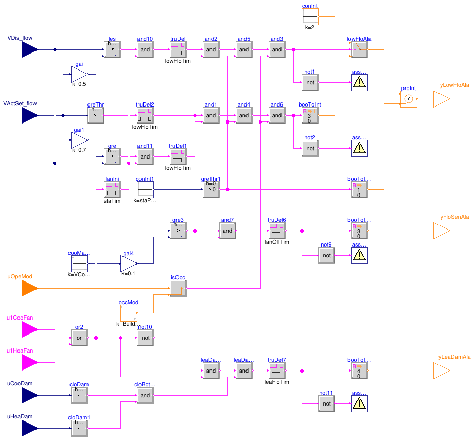
Information
This block outputs alarms of dual-duct terminal unit using mixing control with discharge flow sensor.
The implementation is according to the Section 5.13.6 of ASHRAE Guideline 36, May 2020.
Low airflow
-
If the zone is in occupied mode and after the AHU supply fan has been enabled for
staTim,
if the measured airflow VDis_flow is less than 70% of setpoint
VActSet_flow for 5 minutes (lowFloTim) while the setpoint
is greater than zero, generate a Level 3 alarm.
-
If the zone is in occupied mode and after the AHU supply fan has been enabled for
staTim,
if the measured airflow VDis_flow is less than 50% of setpoint
VActSet_flow for 5 minutes (lowFloTim) while the setpoint
is greater than zero, generate a Level 2 alarm.
-
If a zone has an importance multiplier (
staPreMul) of 0 for its
static pressure reset Trim-Respond control loop, low airflow alarms shall be
suppressed for that zone.
Airflow sensor calibration
-
If the cooling and heating fans serving the zone have been OFF (
u1CooFan=false
and u1HeaFan=false) for 10 minutes (fanOffTim), and the
discharge airflow sensor reading VDis_flow
is above 10% of the cooling maximum airflow setpoint VCooMax_flow,
generate a Level 3 alarm.
Leaking damper
-
If the cooling and heating damper position (
uCooDam and uHeaDam)
are 0% and airflow sensor reading
VDis_flow is above 10% of the cooling maximum airflow setpoint
VCooMax_flow for 10 minutes (leaFloTim) while the
fan serving the zone is proven on (u1CooFan=true or u1HeaFan=true),
generate a Level 4 alarm.
Parameters
| Type | Name | Default | Description |
|---|
| Real | staPreMul | | Importance multiplier for the zone static pressure reset control loop |
| Real | VCooMax_flow | | Design zone cooling maximum airflow rate [m3/s] |
| Real | lowFloTim | 300 | Threshold time to check low flow rate [s] |
| Real | fanOffTim | 600 | Threshold time to check fan off [s] |
| Real | leaFloTim | 600 | Threshold time to check damper leaking airflow [s] |
| Advanced |
| Real | floHys | 0.05 | Near zero flow rate, below which the flow rate or difference will be seen as zero [m3/s] |
| Real | damPosHys | 0.05 | Near zero damper position, below which the damper will be seen as closed [1] |
| Real | staTim | 1800 | Delay triggering alarms after enabling AHU supply fan [s] |
Connectors
| Type | Name | Description |
|---|
| input RealInput | VDis_flow | Measured discharge airflow rate [m3/s] |
| input RealInput | VActSet_flow | Active airflow setpoint [m3/s] |
| input IntegerInput | uOpeMod | Zone operation mode |
| input BooleanInput | u1CooFan | Cooling air handler supply fan status |
| input BooleanInput | u1HeaFan | Heating air handler supply fan status |
| input RealInput | uCooDam | Cooling damper position setpoint [1] |
| input RealInput | uHeaDam | Heating damper position setpoint [1] |
| output IntegerOutput | yLowFloAla | Low airflow alarms |
| output IntegerOutput | yFloSenAla | Airflow sensor calibration alarm |
| output IntegerOutput | yLeaDamAla | Leaking dampers alarm, could be heating or cooling damper |
Modelica definition
block Alarms
parameter Real staPreMul
;
parameter Real VCooMax_flow(
final quantity="VolumeFlowRate",
final unit="m3/s")
;
parameter Real lowFloTim(
final unit="s",
final quantity="Time")=300
;
parameter Real fanOffTim(
final unit="s",
final quantity="Time")=600
;
parameter Real leaFloTim(
final unit="s",
final quantity="Time")=600
;
parameter Real floHys(
final quantity="VolumeFlowRate",
final unit="m3/s")=0.05
;
parameter Real damPosHys(
final unit="1")=0.05
;
parameter Real staTim(
final unit="s",
final quantity="Time")=1800
;
Buildings.Controls.OBC.CDL.Interfaces.RealInput VDis_flow(
final min=0,
final unit="m3/s",
final quantity="VolumeFlowRate") ;
Buildings.Controls.OBC.CDL.Interfaces.RealInput VActSet_flow(
final min=0,
final unit="m3/s",
final quantity="VolumeFlowRate") ;
Buildings.Controls.OBC.CDL.Interfaces.IntegerInput uOpeMod
;
Buildings.Controls.OBC.CDL.Interfaces.BooleanInput u1CooFan
;
Buildings.Controls.OBC.CDL.Interfaces.BooleanInput u1HeaFan
;
Buildings.Controls.OBC.CDL.Interfaces.RealInput uCooDam(
final min=0,
final unit="1")
;
Buildings.Controls.OBC.CDL.Interfaces.RealInput uHeaDam(
final min=0,
final unit="1")
;
Buildings.Controls.OBC.CDL.Interfaces.IntegerOutput yLowFloAla
;
Buildings.Controls.OBC.CDL.Interfaces.IntegerOutput yFloSenAla
;
Buildings.Controls.OBC.CDL.Interfaces.IntegerOutput yLeaDamAla
;
Buildings.Controls.OBC.CDL.Reals.MultiplyByParameter gai(
final k=0.5)
;
Buildings.Controls.OBC.CDL.Reals.Less les(
final h=floHys)
;
Buildings.Controls.OBC.CDL.Logical.TrueDelay truDel(
final delayTime=lowFloTim)
;
Buildings.Controls.OBC.CDL.Reals.GreaterThreshold greThr(
final t=floHys,
final h=0.5*floHys)
;
Buildings.Controls.OBC.CDL.Reals.Greater gre(
final h=floHys)
;
Buildings.Controls.OBC.CDL.Reals.MultiplyByParameter gai1(
final k=0.7)
;
Buildings.Controls.OBC.CDL.Logical.TrueDelay truDel1(
final delayTime=lowFloTim)
;
Buildings.Controls.OBC.CDL.Logical.And and2
;
Buildings.Controls.OBC.CDL.Logical.And and1
;
Buildings.Controls.OBC.CDL.Integers.Switch lowFloAla
;
Buildings.Controls.OBC.CDL.Integers.Sources.Constant conInt(
final k=2)
;
Buildings.Controls.OBC.CDL.Conversions.BooleanToInteger booToInt(
final integerTrue=3)
;
Buildings.Controls.OBC.CDL.Reals.Sources.Constant conInt1(
final k=staPreMul)
;
Buildings.Controls.OBC.CDL.Reals.GreaterThreshold greThr1
;
Buildings.Controls.OBC.CDL.Conversions.BooleanToInteger booToInt1
;
Buildings.Controls.OBC.CDL.Integers.Multiply proInt
;
Buildings.Controls.OBC.CDL.Logical.And and5
;
Buildings.Controls.OBC.CDL.Logical.Not not1
;
Buildings.Controls.OBC.CDL.Utilities.Assert assMes(
final message="Warning: airflow is less than 50% of the setpoint.")
;
Buildings.Controls.OBC.CDL.Logical.And and4
;
Buildings.Controls.OBC.CDL.Logical.Not not2
;
Buildings.Controls.OBC.CDL.Utilities.Assert assMes1(
final message="Warning: airflow is less than 70% of the setpoint.")
;
Buildings.Controls.OBC.CDL.Reals.LessThreshold cloDam(
final t=damPosHys,
final h=0.5*damPosHys) ;
Buildings.Controls.OBC.CDL.Reals.LessThreshold cloDam1(
final t=damPosHys,
final h=0.5*damPosHys)
;
Buildings.Controls.OBC.CDL.Reals.Sources.Constant cooMaxFlo1(
final k=VCooMax_flow)
;
Buildings.Controls.OBC.CDL.Reals.MultiplyByParameter gai4(
final k=0.1)
;
Buildings.Controls.OBC.CDL.Reals.Greater gre3(
final h=floHys)
;
Buildings.Controls.OBC.CDL.Logical.And and7
;
Buildings.Controls.OBC.CDL.Logical.Not not9
;
Buildings.Controls.OBC.CDL.Utilities.Assert assMes6(
final message="Warning: airflow sensor should be calibrated.")
;
Buildings.Controls.OBC.CDL.Conversions.BooleanToInteger booToInt6(
final integerTrue=3)
;
Buildings.Controls.OBC.CDL.Logical.Or or2
;
Buildings.Controls.OBC.CDL.Logical.TrueDelay truDel6(
final delayTime=fanOffTim)
;
Buildings.Controls.OBC.CDL.Logical.Not not10
;
Buildings.Controls.OBC.CDL.Logical.TrueDelay truDel7(
final delayTime=leaFloTim)
;
Buildings.Controls.OBC.CDL.Logical.And leaDamAla2
;
Buildings.Controls.OBC.CDL.Logical.And cloBotDam
;
Buildings.Controls.OBC.CDL.Logical.Not not11
;
Buildings.Controls.OBC.CDL.Utilities.Assert assMes7(
final message="Warning: the cold-duct or hot-dcut damper is leaking.")
;
Buildings.Controls.OBC.CDL.Conversions.BooleanToInteger booToInt7(
final integerTrue=4)
;
Buildings.Controls.OBC.CDL.Logical.TrueDelay truDel2(
final delayTime=lowFloTim)
;
Buildings.Controls.OBC.CDL.Logical.And and10
;
Buildings.Controls.OBC.CDL.Logical.And and11
;
Buildings.Controls.OBC.CDL.Logical.TrueDelay fanIni(
final delayTime=staTim)
;
Buildings.Controls.OBC.CDL.Integers.Sources.Constant occMod(
final k=Buildings.Controls.OBC.ASHRAE.G36.Types.OperationModes.occupied)
;
Buildings.Controls.OBC.CDL.Integers.Equal isOcc
;
Buildings.Controls.OBC.CDL.Logical.And and3
;
Buildings.Controls.OBC.CDL.Logical.And and6
;
Buildings.Controls.OBC.CDL.Logical.And leaDamAla1
;
equation
connect(VActSet_flow, gai.u);
connect(VDis_flow, les.u1);
connect(VActSet_flow, greThr.u);
connect(VActSet_flow, gai1.u);
connect(VDis_flow, gre.u2);
connect(gai1.y, gre.u1);
connect(truDel.y, and2.u1);
connect(truDel1.y, and1.u2);
connect(conInt.y, lowFloAla.u1);
connect(booToInt.y, lowFloAla.u3);
connect(conInt1.y, greThr1.u);
connect(greThr1.y, booToInt1.u);
connect(lowFloAla.y, proInt.u1);
connect(booToInt1.y, proInt.u2);
connect(not1.y, assMes.u);
connect(and2.y,and5. u1);
connect(greThr1.y,and5. u2);
connect(and1.y, and4.u1);
connect(greThr1.y, and4.u2);
connect(not2.y, assMes1.u);
connect(proInt.y, yLowFloAla);
connect(uCooDam, cloDam.u);
connect(uHeaDam, cloDam1.u);
connect(VDis_flow, gre3.u1);
connect(gre3.y, and7.u1);
connect(u1CooFan, or2.u1);
connect(u1HeaFan, or2.u2);
connect(or2.y, not10.u);
connect(not9.y, assMes6.u);
connect(booToInt6.y, yFloSenAla);
connect(gai4.y, gre3.u2);
connect(cooMaxFlo1.y, gai4.u);
connect(or2.y, leaDamAla2.u2);
connect(cloDam.y, cloBotDam.u1);
connect(cloDam1.y, cloBotDam.u2);
connect(not11.y, assMes7.u);
connect(booToInt7.y, yLeaDamAla);
connect(greThr.y, truDel2.u);
connect(truDel2.y, and1.u1);
connect(truDel2.y, and2.u2);
connect(not10.y, and7.u2);
connect(and7.y, truDel6.u);
connect(truDel6.y, booToInt6.u);
connect(truDel6.y, not9.u);
connect(truDel7.y, booToInt7.u);
connect(truDel7.y, not11.u);
connect(gre3.y, leaDamAla2.u1);
connect(les.y, and10.u1);
connect(and10.y, truDel.u);
connect(gre.y, and11.u1);
connect(and11.y, truDel1.u);
connect(or2.y, fanIni.u);
connect(fanIni.y, and10.u2);
connect(fanIni.y, and11.u2);
connect(occMod.y, isOcc.u2);
connect(uOpeMod, isOcc.u1);
connect(gai.y, les.u2);
connect(and5.y, and3.u1);
connect(and3.y, lowFloAla.u2);
connect(and3.y, not1.u);
connect(and6.y, booToInt.u);
connect(and6.y, not2.u);
connect(and4.y, and6.u1);
connect(isOcc.y, and3.u2);
connect(isOcc.y, and6.u2);
connect(leaDamAla2.y, leaDamAla1.u1);
connect(leaDamAla1.y, truDel7.u);
connect(cloBotDam.y, leaDamAla1.u2);
end Alarms;
Output signals for controlling dampers of dual-duct terminal unit using mixing control with discharge flow sensor
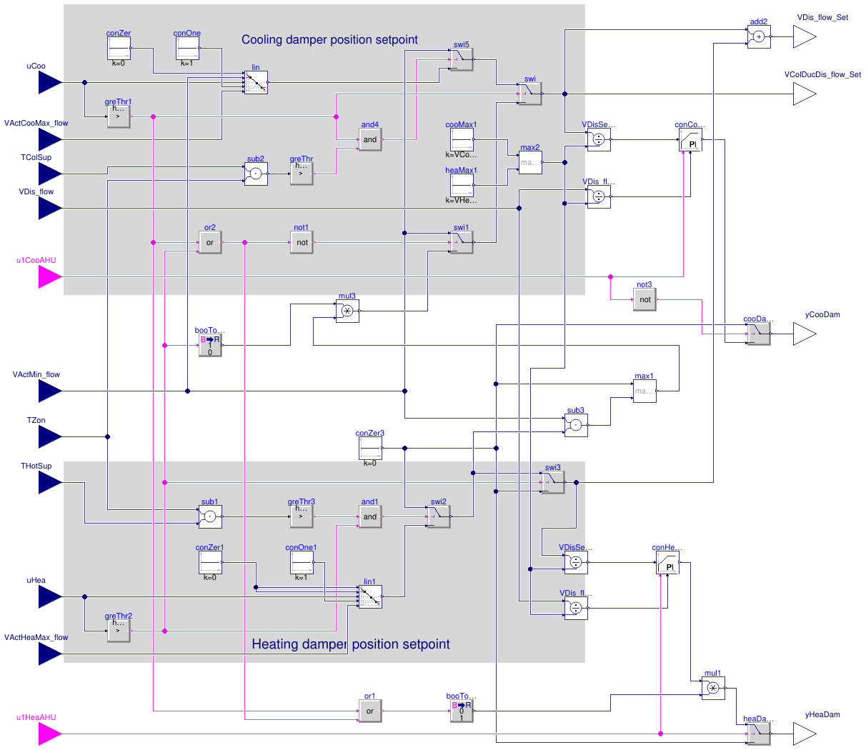
Information
This sequence sets the dampers for dual-duct terminal unit using mixing control with
discharge flow sensor.
The implementation is according to Section 5.13.5 of ASHRAE Guideline 36, May 2020. The
calculation is done following the steps below.
-
When the zone state is cooling (
uCoo > 0), then the cooling loop output
uCoo shall reset the supply airflow setpoint from the minimum VActMin_flow to
cooling maximum setpoint VActCooMax_flow. The cooling damper shall be
modulated by a control loop to maintain the measured aiflow
VDis_flow at setpoint. The heating damper shall be closed
yHeaDam=0.
-
If the cold-deck supply air temperature
TColSup from the cooling air handler
is greater than room temperature TZon, cooling supply airflow setpoint shall be
no higher than the minimum.
-
When the zone state is deadband (
uCoo=0 and uHea=0), the cooling
airflow set point VColDucDis_flow_Set shall be the minimum set point
VActMin_flow. The cooling damper shall be modulated by a control loop
to maintain the measured cooling airflow at set point. The heating damper shall be closed.
-
When the zone state is heating (
uHea > 0), then the heating loop output
uHea shall be mapped to the heating damper position.
The cooling damper is modulated to maintain measured discharge airflow at the minimum airflow
setpoint VActMin_flow.
-
If the hot-deck supply air temperature
THotSup from the heating air handler
is less than room temperature TZon, the heating damper shall be closed.
-
Maximum heating airflow shall be limited by a reverse-acting P-only loop whose setpoint
is the heating maximum
VActHeaMax_flow and whose output is maximum heating
damper position rangingfrom 0% to 100%.
-
Overriding above controls:
-
If heating air handler is not proven ON (
u1HeaAHU=false), the heating
damper shall be closed (yHeaDam=0).
-
If cooling air handler is not proven ON (
u1CooAHU=false), the cooling
damper shall be closed (yCooDam=0).
The sequences of controlling dampers position for dual-duct terminal unit
using mixing control with inlet flow sensor are described in the following figure below.
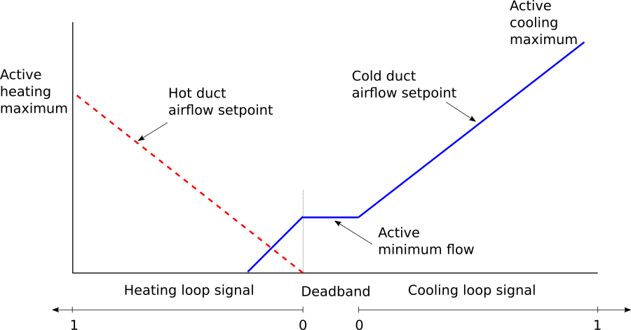
Note that when the zone is in heating state, the wordings in Section 5.13.5.1.c does
not specify the flow setpoint. This causes confusion when implementing system request
sequences that is specified in Section 5.13.8.4, which requires the flow setpoint. To
avoid the confusion, the sequence was then implemented according to the plot above,
which is Figure 5.13.5 in Guideline 36.
Parameters
| Type | Name | Default | Description |
|---|
| Real | VCooMax_flow | | Design zone cooling maximum airflow rate [m3/s] |
| Real | VHeaMax_flow | | Design zone heating maximum airflow rate [m3/s] |
| SimpleController | controllerTypeDam | Buildings.Controls.OBC.CDL.T... | Type of controller |
| Real | kDam | 0.5 | Gain of controller for damper control [1] |
| Real | TiDam | 300 | Time constant of integrator block for damper control [s] |
| Real | TdDam | 0.1 | Time constant of derivative block for damper control [s] |
| Real | kHeaMaxDam | 0.5 | Gain of controller for heating maximum damper control [1] |
| Advanced |
| Real | dTHys | 0.25 | Temperature difference hysteresis below which the temperature difference will be seen as zero [K] |
| Real | looHys | 0.05 | Loop output hysteresis below which the output will be seen as zero [1] |
| Real | iniDam | 0.01 | Initial damper position when the damper control is enabled [1] |
Connectors
| Type | Name | Description |
|---|
| input RealInput | uCoo | Cooling control signal [1] |
| input RealInput | VActCooMax_flow | Active cooling maximum airflow rate [m3/s] |
| input RealInput | TColSup | Cold duct supply air temperature from central air handler [K] |
| input RealInput | VDis_flow | Measured discharge airflow rate airflow rate [m3/s] |
| input BooleanInput | u1CooAHU | Cooling air handler status |
| input RealInput | VActMin_flow | Active minimum airflow rate [m3/s] |
| input RealInput | TZon | Measured zone temperature [K] |
| input RealInput | THotSup | Hot duct supply air temperature from central air handler [K] |
| input RealInput | uHea | Heating control signal [1] |
| input RealInput | VActHeaMax_flow | Active heating maximum airflow rate [m3/s] |
| input BooleanInput | u1HeaAHU | Heating air handler status |
| output RealOutput | VDis_flow_Set | Discharge airflow setpoint [m3/s] |
| output RealOutput | VColDucDis_flow_Set | Cold duct discharge airflow setpoint [m3/s] |
| output RealOutput | yCooDam | Cold duct damper commanded position [1] |
| output RealOutput | yHeaDam | Hot duct damper commanded position [1] |
Modelica definition
block Dampers
parameter Real VCooMax_flow(
final quantity="VolumeFlowRate",
final unit="m3/s")
;
parameter Real VHeaMax_flow(
final quantity="VolumeFlowRate",
final unit="m3/s")
;
parameter Buildings.Controls.OBC.CDL.Types.SimpleController controllerTypeDam=
Buildings.Controls.OBC.CDL.Types.SimpleController.PI
;
parameter Real kDam(
final unit="1")=0.5
;
parameter Real TiDam(
final unit="s",
final quantity="Time")=300
;
parameter Real TdDam(
final unit="s",
final quantity="Time")=0.1
;
parameter Real kHeaMaxDam(
final unit="1")=0.5
;
parameter Real dTHys(
final unit="K",
final quantity="TemperatureDifference")=0.25
;
parameter Real looHys(
final unit="1") = 0.05
;
parameter Real iniDam(unit="1")=0.01
;
Buildings.Controls.OBC.CDL.Interfaces.RealInput uCoo(
final min=0,
final max=1,
final unit="1")
;
Buildings.Controls.OBC.CDL.Interfaces.RealInput VActCooMax_flow(
final min=0,
final unit="m3/s",
final quantity="VolumeFlowRate")
;
Buildings.Controls.OBC.CDL.Interfaces.RealInput TColSup(
final unit="K",
final displayUnit="degC",
final quantity="ThermodynamicTemperature")
;
Buildings.Controls.OBC.CDL.Interfaces.RealInput VDis_flow(
final min=0,
final unit="m3/s",
final quantity="VolumeFlowRate")
;
Buildings.Controls.OBC.CDL.Interfaces.BooleanInput u1CooAHU
;
Buildings.Controls.OBC.CDL.Interfaces.RealInput VActMin_flow(
final min=0,
final unit="m3/s",
final quantity="VolumeFlowRate")
;
Buildings.Controls.OBC.CDL.Interfaces.RealInput TZon(
final unit="K",
final displayUnit="degC",
final quantity="ThermodynamicTemperature")
;
Buildings.Controls.OBC.CDL.Interfaces.RealInput THotSup(
final unit="K",
final displayUnit="degC",
final quantity="ThermodynamicTemperature")
;
Buildings.Controls.OBC.CDL.Interfaces.RealInput uHea(
final min=0,
final max=1,
final unit="1")
;
Buildings.Controls.OBC.CDL.Interfaces.RealInput VActHeaMax_flow(
final min=0,
final unit="m3/s",
final quantity="VolumeFlowRate")
;
Buildings.Controls.OBC.CDL.Interfaces.BooleanInput u1HeaAHU
;
Buildings.Controls.OBC.CDL.Interfaces.RealOutput VDis_flow_Set(
final min=0,
final unit="m3/s",
final quantity="VolumeFlowRate")
;
Buildings.Controls.OBC.CDL.Interfaces.RealOutput VColDucDis_flow_Set(
final min=0,
final unit="m3/s",
final quantity="VolumeFlowRate")
;
Buildings.Controls.OBC.CDL.Interfaces.RealOutput yCooDam(
final min=0,
final max=1,
final unit="1") ;
Buildings.Controls.OBC.CDL.Interfaces.RealOutput yHeaDam(
final min=0,
final max=1,
final unit="1") ;
Buildings.Controls.OBC.CDL.Logical.And and4 ;
Buildings.Controls.OBC.CDL.Reals.Line lin
;
Buildings.Controls.OBC.CDL.Reals.Switch swi
;
Buildings.Controls.OBC.CDL.Reals.Switch swi5
;
Buildings.Controls.OBC.CDL.Reals.Sources.Constant conZer(
final k=0) ;
Buildings.Controls.OBC.CDL.Reals.Sources.Constant conOne(
final k=1) ;
Buildings.Controls.OBC.CDL.Reals.GreaterThreshold greThr1(
final t=looHys,
final h=0.5*looHys)
;
Buildings.Controls.OBC.CDL.Reals.GreaterThreshold greThr(
final t=dTHys,
final h=0.5*dTHys)
;
Buildings.Controls.OBC.CDL.Reals.Subtract sub2
;
Buildings.Controls.OBC.CDL.Logical.Or or2
;
Buildings.Controls.OBC.CDL.Reals.GreaterThreshold greThr2(
final t=looHys,
final h=0.5*looHys) ;
Buildings.Controls.OBC.CDL.Logical.Not not1
;
Buildings.Controls.OBC.CDL.Reals.Switch swi1
;
Buildings.Controls.OBC.CDL.Reals.Subtract sub1
;
Buildings.Controls.OBC.CDL.Reals.GreaterThreshold greThr3(
final t=dTHys,
final h=0.5*dTHys)
;
Buildings.Controls.OBC.CDL.Logical.And and1
;
Buildings.Controls.OBC.CDL.Reals.Switch swi2
;
Buildings.Controls.OBC.CDL.Reals.Switch swi3
;
Buildings.Controls.OBC.CDL.Reals.Sources.Constant conZer3(
final k=0)
;
Buildings.Controls.OBC.CDL.Reals.Subtract sub3
;
Buildings.Controls.OBC.CDL.Reals.Max max1
;
Buildings.Controls.OBC.CDL.Conversions.BooleanToReal booToRea2(
final realTrue=1,
final realFalse=0)
;
Buildings.Controls.OBC.CDL.Reals.Multiply mul3
;
Buildings.Controls.OBC.CDL.Reals.Divide VDisSet_flowNor
;
Buildings.Controls.OBC.CDL.Reals.PIDWithReset conCooDam(
final controllerType=controllerTypeDam,
final k=kDam,
final Ti=TiDam,
final Td=TdDam,
final yMax=1,
final yMin=0,
final y_reset=iniDam)
;
Buildings.Controls.OBC.CDL.Reals.Divide VDis_flowNor
;
Buildings.Controls.OBC.CDL.Reals.Switch cooDamPos
;
Buildings.Controls.OBC.CDL.Logical.Not not3
;
Buildings.Controls.OBC.CDL.Reals.Divide VDisSet_flowNor1
;
Buildings.Controls.OBC.CDL.Reals.PIDWithReset conHeaDam(
final controllerType=Buildings.Controls.OBC.CDL.Types.SimpleController.P,
final k=kHeaMaxDam,
final yMax=1,
final yMin=0,
final y_reset=0)
;
Buildings.Controls.OBC.CDL.Reals.Divide VDis_flowNor1
;
Buildings.Controls.OBC.CDL.Reals.Switch heaDamPos
;
Buildings.Controls.OBC.CDL.Logical.Or or1
;
Buildings.Controls.OBC.CDL.Conversions.BooleanToReal booToRea1(
final realTrue=0,
final realFalse=1)
;
Buildings.Controls.OBC.CDL.Reals.Multiply mul1
;
Buildings.Controls.OBC.CDL.Reals.Sources.Constant conZer1(
final k=0)
;
Buildings.Controls.OBC.CDL.Reals.Sources.Constant conOne1(
final k=1)
;
Buildings.Controls.OBC.CDL.Reals.Line lin1
;
Buildings.Controls.OBC.CDL.Reals.Add add2
;
Buildings.Controls.OBC.CDL.Reals.Sources.Constant cooMax1(
final k=VCooMax_flow)
;
Buildings.Controls.OBC.CDL.Reals.Sources.Constant heaMax1(
final k=VHeaMax_flow)
;
Buildings.Controls.OBC.CDL.Reals.Max max2
;
equation
connect(uCoo, lin.u);
connect(conZer.y, lin.x1);
connect(conOne.y, lin.x2);
connect(VActCooMax_flow, lin.f2);
connect(uCoo, greThr1.u);
connect(and4.y, swi5.u2);
connect(lin.y, swi5.u3);
connect(swi5.y, swi.u1);
connect(TColSup, sub2.u1);
connect(sub2.y, greThr.u);
connect(greThr.y, and4.u2);
connect(greThr1.y, and4.u1);
connect(greThr1.y, swi.u2);
connect(TZon, sub2.u2);
connect(VActMin_flow, swi5.u1);
connect(greThr1.y, or2.u1);
connect(uHea, greThr2.u);
connect(greThr2.y, or2.u2);
connect(or2.y, not1.u);
connect(not1.y, swi1.u2);
connect(VActMin_flow, swi1.u1);
connect(swi1.y, swi.u3);
connect(TZon, sub1.u1);
connect(THotSup, sub1.u2);
connect(sub1.y, greThr3.u);
connect(greThr3.y, and1.u1);
connect(greThr2.y, and1.u2);
connect(and1.y, swi2.u2);
connect(greThr2.y, swi3.u2);
connect(swi2.y, swi3.u1);
connect(conZer3.y, swi3.u3);
connect(VActMin_flow, sub3.u1);
connect(sub3.y, max1.u2);
connect(conZer3.y, max1.u1);
connect(greThr2.y, booToRea2.u);
connect(booToRea2.y, mul3.u1);
connect(max1.y, mul3.u2);
connect(mul3.y, swi1.u3);
connect(swi.y, VColDucDis_flow_Set);
connect(swi.y, VDisSet_flowNor.u1);
connect(VDisSet_flowNor.y, conCooDam.u_s);
connect(VDis_flow, VDis_flowNor.u1);
connect(VDis_flowNor.y, conCooDam.u_m);
connect(u1CooAHU, conCooDam.trigger);
connect(u1CooAHU, not3.u);
connect(not3.y, cooDamPos.u2);
connect(conCooDam.y, cooDamPos.u3);
connect(conZer3.y, cooDamPos.u1);
connect(cooDamPos.y, yCooDam);
connect(heaDamPos.y, yHeaDam);
connect(u1HeaAHU, heaDamPos.u2);
connect(conZer3.y, heaDamPos.u3);
connect(VDisSet_flowNor1.y, conHeaDam.u_s);
connect(VDis_flowNor1.y, conHeaDam.u_m);
connect(u1HeaAHU, conHeaDam.trigger);
connect(greThr1.y, or1.u1);
connect(or2.y, or1.u2);
connect(or1.y, booToRea1.u);
connect(booToRea1.y, mul1.u2);
connect(mul1.y, heaDamPos.u1);
connect(VActMin_flow, lin.f1);
connect(conZer3.y, swi2.u1);
connect(VDis_flow, VDis_flowNor1.u1);
connect(conZer1.y, lin1.x1);
connect(conZer1.y, lin1.f1);
connect(conOne1.y, lin1.x2);
connect(VActHeaMax_flow, lin1.f2);
connect(uHea, lin1.u);
connect(lin1.y, swi2.u3);
connect(swi2.y, sub3.u2);
connect(swi3.y, VDisSet_flowNor1.u1);
connect(conHeaDam.y, mul1.u1);
connect(swi.y, add2.u1);
connect(swi3.y, add2.u2);
connect(add2.y, VDis_flow_Set);
connect(cooMax1.y,max2. u1);
connect(heaMax1.y,max2. u2);
connect(max2.y, VDisSet_flowNor.u2);
connect(max2.y, VDis_flowNor.u2);
connect(max2.y, VDisSet_flowNor1.u2);
connect(max2.y, VDis_flowNor1.u2);
end Dampers;
Software switches to override setpoints
Information
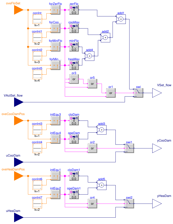
This block considers the overrides to the setpoints for dual-duct terminal unit using
mixing control with discharge flow sensor.
The implementation is according to the Section 5.13.7 of ASHRAE Guideline 36,
May 2020.
Provide software switches that interlock to a system-level point to:
-
when
oveFloSet equals to 1, force the zone airflow setpoint
VSet_flow to zero,
-
when
oveFloSet equals to 2, force the zone airflow setpoint
VSet_flow to zone cooling maximum airflow rate
VCooMax_flow,
-
when
oveFloSet equals to 3, force the zone airflow setpoint
VSet_flow to zone minimum airflow setpoint
VMin_flow.
-
when
oveFloSet equals to 4, force the zone airflow setpoint
VSet_flow to zone heating maximum airflow setpoint
VHeaMax_flow.
-
when
oveCooDamPos equals to 1, force the cooling damper to full closed by setting
yCooDam to 0,
-
when
oveCooDamPos equals to 2, force the cooling damper to full open by setting
yCooDam to 1.
-
when
oveHeaDamPos equals to 1, force the heating damper to full closed by setting
yHeaDam to 0,
-
when
oveHeaDamPos equals to 2, force the heating damper to full open by setting
yHeaDam to 1.
Parameters
| Type | Name | Default | Description |
|---|
| Real | VMin_flow | | Design zone minimum airflow setpoint [m3/s] |
| Real | VCooMax_flow | | Design zone cooling maximum airflow rate [m3/s] |
| Real | VHeaMax_flow | | Design zone heating maximum airflow rate [m3/s] |
Connectors
| Type | Name | Description |
|---|
| input IntegerInput | oveFloSet | Index of overriding flow setpoint, 1: set to zero; 2: set to cooling maximum; 3: set to minimum flow; 4: set to heating maximum |
| input RealInput | VActSet_flow | Active airflow setpoint [m3/s] |
| input IntegerInput | oveCooDamPos | Index of overriding cooling damper position, 1: set to close; 2: set to open |
| input RealInput | uCooDam | Cooling damper commanded position [1] |
| input IntegerInput | oveHeaDamPos | Index of overriding heating damper position, 1: set to close; 2: set to open |
| input RealInput | uHeaDam | Heating damper commanded position [1] |
| output RealOutput | VSet_flow | Airflow setpoint after considering override [m3/s] |
| output RealOutput | yCooDam | Cooling damper position setpoint after considering override [1] |
| output RealOutput | yHeaDam | Heating damper position setpoint after considering override [1] |
Modelica definition
block Overrides
parameter Real VMin_flow(
final quantity="VolumeFlowRate",
final unit="m3/s")
;
parameter Real VCooMax_flow(
final quantity="VolumeFlowRate",
final unit="m3/s")
;
parameter Real VHeaMax_flow(
final quantity="VolumeFlowRate",
final unit="m3/s")
;
Buildings.Controls.OBC.CDL.Interfaces.IntegerInput oveFloSet
;
Buildings.Controls.OBC.CDL.Interfaces.RealInput VActSet_flow(
final min=0,
final unit="m3/s",
final quantity="VolumeFlowRate")
;
Buildings.Controls.OBC.CDL.Interfaces.IntegerInput oveCooDamPos
;
Buildings.Controls.OBC.CDL.Interfaces.RealInput uCooDam(
final min=0,
final unit="1")
;
Buildings.Controls.OBC.CDL.Interfaces.IntegerInput oveHeaDamPos
;
Buildings.Controls.OBC.CDL.Interfaces.RealInput uHeaDam(
final min=0,
final unit="1")
;
Buildings.Controls.OBC.CDL.Interfaces.RealOutput VSet_flow(
final min=0,
final unit="m3/s",
final quantity="VolumeFlowRate")
;
Buildings.Controls.OBC.CDL.Interfaces.RealOutput yCooDam(
final min=0,
final unit="1")
;
Buildings.Controls.OBC.CDL.Interfaces.RealOutput yHeaDam(
final min=0,
final unit="1")
;
protected
Buildings.Controls.OBC.CDL.Integers.Sources.Constant conInt(
final k=1)
;
Buildings.Controls.OBC.CDL.Integers.Equal forZerFlo ;
Buildings.Controls.OBC.CDL.Integers.Equal forCooMax
;
Buildings.Controls.OBC.CDL.Integers.Sources.Constant conInt1(
final k=2)
;
Buildings.Controls.OBC.CDL.Integers.Equal forMinFlo
;
Buildings.Controls.OBC.CDL.Integers.Sources.Constant conInt2(
final k=3)
;
Buildings.Controls.OBC.CDL.Conversions.BooleanToReal zerFlo(
final realTrue=0)
;
Buildings.Controls.OBC.CDL.Conversions.BooleanToReal cooMax(
final realTrue=VCooMax_flow)
;
Buildings.Controls.OBC.CDL.Conversions.BooleanToReal minFlo(
final realTrue=VMin_flow)
;
Buildings.Controls.OBC.CDL.Reals.Add add2 ;
Buildings.Controls.OBC.CDL.Reals.Add add1 ;
Buildings.Controls.OBC.CDL.Reals.Switch swi
;
Buildings.Controls.OBC.CDL.Logical.Or or3
;
Buildings.Controls.OBC.CDL.Integers.Sources.Constant conInt3(
final k=1)
;
Buildings.Controls.OBC.CDL.Integers.Equal intEqu3
;
Buildings.Controls.OBC.CDL.Integers.Equal intEqu4
;
Buildings.Controls.OBC.CDL.Integers.Sources.Constant conInt4(
final k=2)
;
Buildings.Controls.OBC.CDL.Conversions.BooleanToReal cloDam(
final realTrue=0)
;
Buildings.Controls.OBC.CDL.Conversions.BooleanToReal opeDam(
final realTrue=1)
;
Buildings.Controls.OBC.CDL.Reals.Add add3 ;
Buildings.Controls.OBC.CDL.Logical.Or or2
;
Buildings.Controls.OBC.CDL.Reals.Switch swi1
;
Buildings.Controls.OBC.CDL.Integers.Sources.Constant conInt5(
final k=4)
;
Buildings.Controls.OBC.CDL.Integers.Equal forMinFlo1
;
Buildings.Controls.OBC.CDL.Conversions.BooleanToReal heaMax(
final realTrue=VHeaMax_flow)
;
Buildings.Controls.OBC.CDL.Reals.Add add4
;
Buildings.Controls.OBC.CDL.Logical.Or or1
;
Buildings.Controls.OBC.CDL.Integers.Sources.Constant conInt6(
final k=1)
;
Buildings.Controls.OBC.CDL.Integers.Equal intEqu1
;
Buildings.Controls.OBC.CDL.Integers.Equal intEqu2
;
Buildings.Controls.OBC.CDL.Integers.Sources.Constant conInt7(
final k=2)
;
Buildings.Controls.OBC.CDL.Conversions.BooleanToReal cloDam1(
final realTrue=0)
;
Buildings.Controls.OBC.CDL.Conversions.BooleanToReal opeDam1(
final realTrue=1)
;
Buildings.Controls.OBC.CDL.Reals.Add add5
;
Buildings.Controls.OBC.CDL.Logical.Or or4
;
Buildings.Controls.OBC.CDL.Reals.Switch swi2
;
Buildings.Controls.OBC.CDL.Logical.Or or5
;
equation
connect(oveFloSet, forZerFlo.u1);
connect(conInt.y, forZerFlo.u2);
connect(oveFloSet, forCooMax.u1);
connect(conInt1.y, forCooMax.u2);
connect(oveFloSet, forMinFlo.u1);
connect(conInt2.y, forMinFlo.u2);
connect(forZerFlo.y, zerFlo.u);
connect(forCooMax.y, cooMax.u);
connect(forMinFlo.y, minFlo.u);
connect(cooMax.y, add2.u1);
connect(zerFlo.y, add1.u1);
connect(forZerFlo.y, or3.u1);
connect(forCooMax.y, or3.u2);
connect(add1.y, swi.u1);
connect(VActSet_flow, swi.u3);
connect(swi.y, VSet_flow);
connect(conInt3.y, intEqu3.u2);
connect(conInt4.y,intEqu4. u2);
connect(oveCooDamPos, intEqu3.u1);
connect(oveCooDamPos, intEqu4.u1);
connect(intEqu3.y, cloDam.u);
connect(intEqu4.y, opeDam.u);
connect(cloDam.y, add3.u1);
connect(opeDam.y, add3.u2);
connect(intEqu3.y, or2.u1);
connect(intEqu4.y, or2.u2);
connect(add3.y, swi1.u1);
connect(or2.y, swi1.u2);
connect(uCooDam, swi1.u3);
connect(swi1.y, yCooDam);
connect(oveFloSet, forMinFlo1.u1);
connect(conInt5.y, forMinFlo1.u2);
connect(forMinFlo1.y, heaMax.u);
connect(add2.y, add1.u2);
connect(minFlo.y, add4.u1);
connect(heaMax.y, add4.u2);
connect(add4.y, add2.u2);
connect(forMinFlo1.y, or1.u2);
connect(or1.y, swi.u2);
connect(conInt6.y,intEqu1. u2);
connect(conInt7.y,intEqu2. u2);
connect(oveHeaDamPos, intEqu1.u1);
connect(oveHeaDamPos, intEqu2.u1);
connect(intEqu1.y, cloDam1.u);
connect(intEqu2.y, opeDam1.u);
connect(cloDam1.y, add5.u1);
connect(opeDam1.y, add5.u2);
connect(intEqu1.y,or4. u1);
connect(intEqu2.y,or4. u2);
connect(add5.y,swi2. u1);
connect(or4.y,swi2. u2);
connect(uHeaDam, swi2.u3);
connect(swi2.y, yHeaDam);
connect(or3.y, or5.u1);
connect(or5.y, or1.u1);
connect(forMinFlo.y, or5.u2);
end Overrides;
Output system requests for dual-duct unit using mixing control with discharge flow sensor
Information
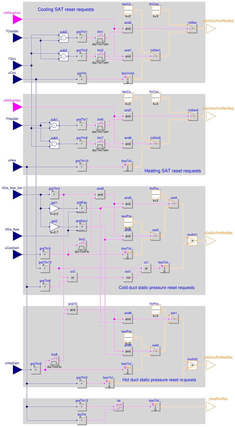
This sequence outputs the system reset requests for dual-duct terminal unit using
mixing control with discharge flow sensor. The implementation is according to the Section
5.13.8 of ASHRAE Guideline 36, May 2020.
Cooling SAT reset requests yZonCooTemResReq
-
If the zone temperature
TZon exceeds the zone cooling setpoint
TCooSet by 3 °C (5 °F)) for 2 minutes and after suppression
period (uAftSupCoo=true) due to setpoint change per G36 Part 5.1.20,
send 3 requests (yZonCooTemResReq=3).
-
Else if the zone temperature
TZon exceeds the zone cooling setpoint
TCooSet by 2 °C (3 °F) for 2 minutes and after suppression
period (uAftSupCoo=true) due to setpoint change per G36 Part 5.1.20,
send 2 requests (yZonCooTemResReq=3).
-
Else if the cooling loop
uCoo is greater than 95%, send 1 request
(yZonCooTemResReq=1) until uCoo is less than 85%.
-
Else if
uCoo is less than 95%, send 0 request (yZonCooTemResReq=0).
Cold-duct static pressure reset requests yColDucPreResReq
When the zone is in cooling or deadband state:
-
If the measured airflow
VDis_flow is less than 50% of setpoint
VDis_flow_Set while the setpoint is greater than zero and the damper position
uCooDam is greater than 95% for 1 minute, send 3 requests (yColDucPreResReq=3).
-
Else if the measured airflow
VDis_flow is less than 70% of setpoint
VDis_flow_Set while the setpoint is greater than zero and the damper position
uCooDam is greater than 95% for 1 minute, send 2 requests (yColDucPreResReq=2).
-
Else if the damper position
uCooDam is greater than 95%, send 1 request
(yColDucPreResReq=1) until uDam is less than 85%.
-
Else if the damper position
uCooDam is less than 95%, send 0 request
(yColDucPreResReq=0).
Heating SAT reset requests yZonHeaTemResReq
-
If the zone temperature
TZon is below the zone heating setpoint
THeaSet by 3 °C (5 °F)) for 2 minutes and after suppression
period (uAftSupHea=true) due to setpoint change per G36 Part 5.1.20,
send 3 requests (yZonHeaTemResReq=3).
-
Else if the zone temperature
TZon is below the zone heating setpoint
THeaSet by 2 °C (3 °F) for 2 minutes and after suppression
period (uAftSupHea=true) due to setpoint change per G36 Part 5.1.20,
send 2 requests (yZonHeaTemResReq=3).
-
Else if the heating loop
uHea is greater than 95%, send 1 request
(yZonHeaTemResReq=1) until uHea is less than 85%.
-
Else if
uHea is less than 95%, send 0 request (yZonHeaTemResReq=0).
Hot-duct static pressure reset requests yHotDucPreResReq
When the zone is in heating state:
-
If the measured airflow
VDis_flow is less than 50% of setpoint
VDis_flow_Set while the setpoint is greater than zero and the damper position
uHeaDam is greater than 95% for 1 minute, send 3 requests (yHotDucPreResReq=3).
-
Else if the measured airflow
VDis_flow is less than 70% of setpoint
VDis_flow_Set while the setpoint is greater than zero and the damper position
uHeaDam is greater than 95% for 1 minute, send 2 requests (yHotDucPreResReq=2).
-
Else if the damper position
uHeaDam is greater than 95%, send 1 request
(yHotDucPreResReq=1) until uHeaDam is less than 85%.
-
Else if the damper position
uHeaDam is less than 95%, send 0 request
(yHotDucPreResReq=0).
Heating-fan requests
Send the heating fan that serves the zone a heating-fan request as follows:
-
If the heating loop is greater than 15%, send 1 request until the heating loop is
less than 1%.
-
Else if the heatling loop is less than 15%, send 0 requests.
Parameters
| Type | Name | Default | Description |
|---|
| Real | thrTemDif | 3 | Threshold difference between zone temperature and cooling setpoint for generating 3 cooling SAT reset requests [K] |
| Real | twoTemDif | 2 | Threshold difference between zone temperature and cooling setpoint for generating 2 cooling SAT reset requests [K] |
| Duration times |
| Real | durTimTem | 120 | Duration time of zone temperature exceeds setpoint [s] |
| Real | durTimFlo | 60 | Duration time of airflow rate less than setpoint [s] |
| Advanced |
| Real | dTHys | 0.25 | Near zero temperature difference, below which the difference will be seen as zero [K] |
| Real | floHys | | Near zero flow rate, below which the flow rate or difference will be seen as zero [m3/s] |
| Real | looHys | | Loop output hysteresis below which the output will be seen as zero [1] |
| Real | damPosHys | | Near zero damper position, below which the damper will be seen as closed [1] |
Connectors
| Type | Name | Description |
|---|
| input BooleanInput | uAftSupCoo | After suppression period due to the cooling setpoint change |
| input RealInput | TCooSet | Zone cooling setpoint temperature [K] |
| input RealInput | TZon | Zone temperature [K] |
| input RealInput | uCoo | Cooling loop signal [1] |
| input BooleanInput | uAftSupHea | After suppression period due to the heating setpoint change |
| input RealInput | THeaSet | Zone heating setpoint temperature [K] |
| input RealInput | uHea | Heating loop signal [1] |
| input RealInput | VDis_flow_Set | Discharge airflow rate setpoint [m3/s] |
| input RealInput | VDis_flow | Measured discharge airflow rate [m3/s] |
| input RealInput | uCooDam | Cooling damper position setpoint [1] |
| input RealInput | uHeaDam | Heating damper position setpoint [1] |
| output IntegerOutput | yZonCooTemResReq | Zone cooling supply air temperature reset request |
| output IntegerOutput | yColDucPreResReq | Cold duct static pressure reset requests |
| output IntegerOutput | yZonHeaTemResReq | Zone heating supply air temperature reset request |
| output IntegerOutput | yHotDucPreResReq | Hot duct static pressure reset requests |
| output IntegerOutput | yHeaFanReq | Heating fan request |
Modelica definition
block SystemRequests
parameter Real thrTemDif(
final unit="K",
final quantity="TemperatureDifference")=3
;
parameter Real twoTemDif(
final unit="K",
final quantity="TemperatureDifference")=2
;
parameter Real durTimTem(
final unit="s",
final quantity="Time")=120
;
parameter Real durTimFlo(
final unit="s",
final quantity="Time")=60
;
parameter Real dTHys(
final unit="K",
final quantity="TemperatureDifference")=0.25
;
parameter Real floHys(
final quantity="VolumeFlowRate",
final unit="m3/s")
;
parameter Real looHys(unit="1")
;
parameter Real damPosHys(
final unit="1")
;
Buildings.Controls.OBC.CDL.Interfaces.BooleanInput uAftSupCoo
;
Buildings.Controls.OBC.CDL.Interfaces.RealInput TCooSet(
final unit="K",
final displayUnit="degC",
final quantity="ThermodynamicTemperature")
;
Buildings.Controls.OBC.CDL.Interfaces.RealInput TZon(
final unit="K",
final displayUnit="degC",
final quantity="ThermodynamicTemperature")
;
Buildings.Controls.OBC.CDL.Interfaces.RealInput uCoo(
final min=0,
final max=1,
final unit="1") ;
Buildings.Controls.OBC.CDL.Interfaces.BooleanInput uAftSupHea
;
Buildings.Controls.OBC.CDL.Interfaces.RealInput THeaSet(
final unit="K",
final displayUnit="degC",
final quantity="ThermodynamicTemperature")
;
Buildings.Controls.OBC.CDL.Interfaces.RealInput uHea(
final min=0,
final max=1,
final unit="1")
;
Buildings.Controls.OBC.CDL.Interfaces.RealInput VDis_flow_Set(
final min=0,
final unit="m3/s",
quantity="VolumeFlowRate")
;
Buildings.Controls.OBC.CDL.Interfaces.RealInput VDis_flow(
final min=0,
final unit="m3/s",
final quantity="VolumeFlowRate")
;
Buildings.Controls.OBC.CDL.Interfaces.RealInput uCooDam(
final min=0,
final max=1,
final unit="1") ;
Buildings.Controls.OBC.CDL.Interfaces.RealInput uHeaDam(
final min=0,
final max=1,
final unit="1") ;
Buildings.Controls.OBC.CDL.Interfaces.IntegerOutput yZonCooTemResReq
;
Buildings.Controls.OBC.CDL.Interfaces.IntegerOutput yColDucPreResReq
;
Buildings.Controls.OBC.CDL.Interfaces.IntegerOutput yZonHeaTemResReq
;
Buildings.Controls.OBC.CDL.Interfaces.IntegerOutput yHotDucPreResReq
;
Buildings.Controls.OBC.CDL.Interfaces.IntegerOutput yHeaFanReq
;
protected
Buildings.Controls.OBC.CDL.Reals.GreaterThreshold greThr1(
final t=thrTemDif,
final h=dTHys)
;
Buildings.Controls.OBC.CDL.Reals.GreaterThreshold greThr2(
final t=twoTemDif,
final h=dTHys)
;
Buildings.Controls.OBC.CDL.Reals.GreaterThreshold greThr3(
final t=0.95,
final h=damPosHys)
;
Buildings.Controls.OBC.CDL.Reals.GreaterThreshold greThr(
final t=0.95,
final h=looHys)
;
Buildings.Controls.OBC.CDL.Reals.GreaterThreshold greThr4(
final t=floHys,
final h=0.5*floHys)
;
Buildings.Controls.OBC.CDL.Conversions.BooleanToInteger booToInt
;
Buildings.Controls.OBC.CDL.Conversions.BooleanToInteger booToInt1
;
Buildings.Controls.OBC.CDL.Reals.MultiplyByParameter gai1(
final k=0.5)
;
Buildings.Controls.OBC.CDL.Reals.MultiplyByParameter gai2(
final k=0.7)
;
Buildings.Controls.OBC.CDL.Reals.Subtract sub2
;
Buildings.Controls.OBC.CDL.Reals.Subtract sub3
;
Buildings.Controls.OBC.CDL.Logical.And and1
;
Buildings.Controls.OBC.CDL.Logical.And and2
;
Buildings.Controls.OBC.CDL.Logical.And and3
;
Buildings.Controls.OBC.CDL.Logical.And and4
;
Buildings.Controls.OBC.CDL.Integers.Sources.Constant thrCooResReq(
final k=3)
;
Buildings.Controls.OBC.CDL.Integers.Sources.Constant twoCooResReq(
final k=2) ;
Buildings.Controls.OBC.CDL.Integers.Sources.Constant thrPreResReq(
final k=3) ;
Buildings.Controls.OBC.CDL.Integers.Sources.Constant twoPreResReq(
final k=2)
;
Buildings.Controls.OBC.CDL.Integers.Switch intSwi
;
Buildings.Controls.OBC.CDL.Integers.Switch intSwi1
;
Buildings.Controls.OBC.CDL.Integers.Switch swi4
;
Buildings.Controls.OBC.CDL.Integers.Switch swi5
;
Buildings.Controls.OBC.CDL.Logical.TrueDelay tim1(
final delayTime=durTimTem) ;
Buildings.Controls.OBC.CDL.Logical.TrueDelay tim2(
final delayTime=durTimTem) ;
Buildings.Controls.OBC.CDL.Logical.TrueDelay tim3(
final delayTime=durTimFlo) ;
Buildings.Controls.OBC.CDL.Reals.Greater greEqu(
final h=floHys)
;
Buildings.Controls.OBC.CDL.Reals.Greater greEqu1(
final h=floHys)
;
Buildings.Controls.OBC.CDL.Logical.And and5
;
Buildings.Controls.OBC.CDL.Reals.GreaterThreshold greThr7(
final t=thrTemDif,
final h=dTHys)
;
Buildings.Controls.OBC.CDL.Reals.GreaterThreshold greThr8(
final t=twoTemDif,
final h=dTHys)
;
Buildings.Controls.OBC.CDL.Reals.GreaterThreshold greThr9(
final t=0.95,
final h=damPosHys)
;
Buildings.Controls.OBC.CDL.Reals.GreaterThreshold greThr10(
final t=0.95,
final h=looHys) ;
Buildings.Controls.OBC.CDL.Conversions.BooleanToInteger booToInt4
;
Buildings.Controls.OBC.CDL.Conversions.BooleanToInteger booToInt5
;
Buildings.Controls.OBC.CDL.Reals.Subtract sub1
;
Buildings.Controls.OBC.CDL.Reals.Subtract sub4
;
Buildings.Controls.OBC.CDL.Logical.And and6
;
Buildings.Controls.OBC.CDL.Logical.And and7
;
Buildings.Controls.OBC.CDL.Logical.And and8
;
Buildings.Controls.OBC.CDL.Logical.And and9
;
Buildings.Controls.OBC.CDL.Integers.Sources.Constant thrCooResReq1(
final k=3)
;
Buildings.Controls.OBC.CDL.Integers.Sources.Constant twoCooResReq1(
final k=2)
;
Buildings.Controls.OBC.CDL.Integers.Sources.Constant thrPreResReq1(
final k=3)
;
Buildings.Controls.OBC.CDL.Integers.Sources.Constant twoPreResReq1(
final k=2)
;
Buildings.Controls.OBC.CDL.Integers.Switch intSwi4
;
Buildings.Controls.OBC.CDL.Integers.Switch intSwi5
;
Buildings.Controls.OBC.CDL.Integers.Switch swi1
;
Buildings.Controls.OBC.CDL.Integers.Switch swi2
;
Buildings.Controls.OBC.CDL.Logical.TrueDelay tim6(
final delayTime=durTimTem)
;
Buildings.Controls.OBC.CDL.Logical.TrueDelay tim7(
final delayTime=durTimTem)
;
Buildings.Controls.OBC.CDL.Logical.TrueDelay tim8(
final delayTime=durTimFlo)
;
Buildings.Controls.OBC.CDL.Logical.And and10
;
Buildings.Controls.OBC.CDL.Reals.GreaterThreshold greThr12(
final t=0.15,
final h=looHys)
;
Buildings.Controls.OBC.CDL.Logical.Latch lat ;
Buildings.Controls.OBC.CDL.Reals.LessThreshold lesThr(
final t=0.01,
final h=looHys)
;
Buildings.Controls.OBC.CDL.Conversions.BooleanToInteger booToInt6
;
Buildings.Controls.OBC.CDL.Reals.GreaterThreshold greThr5(
final t=looHys,
final h=0.5*looHys)
;
Buildings.Controls.OBC.CDL.Reals.GreaterThreshold greThr6(
final t=looHys,
final h=0.5*looHys)
;
Buildings.Controls.OBC.CDL.Reals.GreaterThreshold greThr13(
final t=looHys,
final h=0.5*looHys)
;
Buildings.Controls.OBC.CDL.Logical.Or or2
;
Buildings.Controls.OBC.CDL.Logical.Not not1
;
Buildings.Controls.OBC.CDL.Logical.Or or1
;
Buildings.Controls.OBC.CDL.Conversions.BooleanToInteger booToInt3
;
Buildings.Controls.OBC.CDL.Integers.Multiply mulInt2
;
Buildings.Controls.OBC.CDL.Conversions.BooleanToInteger booToInt2
;
Buildings.Controls.OBC.CDL.Integers.Multiply mulInt1
;
equation
connect(sub2.y, greThr1.u);
connect(and2.y, intSwi.u2);
connect(sub3.y, greThr2.u);
connect(and1.y, intSwi1.u2);
connect(and3.y, swi4.u2);
connect(and4.y, swi5.u2);
connect(greThr2.y, tim2.u);
connect(tim2.y, and1.u2);
connect(greThr1.y, tim1.u);
connect(tim1.y, and2.u2);
connect(greThr4.u, VDis_flow_Set);
connect(greEqu.u1, gai1.y);
connect(greEqu.y, and3.u2);
connect(gai2.y, greEqu1.u1);
connect(greEqu1.y, and4.u2);
connect(uCoo, greThr.u);
connect(uAftSupCoo, and2.u1);
connect(uAftSupCoo, and1.u1);
connect(thrCooResReq.y, intSwi.u1);
connect(twoCooResReq.y, intSwi1.u1);
connect(intSwi1.y, intSwi.u3);
connect(intSwi.y, yZonCooTemResReq);
connect(greThr.y, booToInt.u);
connect(booToInt.y, intSwi1.u3);
connect(uCooDam, greThr3.u);
connect(VDis_flow_Set, gai1.u);
connect(VDis_flow_Set, gai2.u);
connect(VDis_flow, greEqu.u2);
connect(VDis_flow, greEqu1.u2);
connect(greThr3.y, tim3.u);
connect(greThr4.y, and5.u1);
connect(tim3.y, and5.u2);
connect(and5.y, and3.u1);
connect(and5.y, and4.u1);
connect(greThr3.y, booToInt1.u);
connect(booToInt1.y, swi5.u3);
connect(twoPreResReq.y, swi5.u1);
connect(thrPreResReq.y, swi4.u1);
connect(swi5.y, swi4.u3);
connect(TCooSet, sub3.u2);
connect(TCooSet, sub2.u2);
connect(TZon, sub2.u1);
connect(TZon, sub3.u1);
connect(sub1.y,greThr7. u);
connect(and7.y, intSwi4.u2);
connect(sub4.y,greThr8. u);
connect(and6.y,intSwi5. u2);
connect(and8.y,swi1. u2);
connect(and9.y,swi2. u2);
connect(greThr8.y,tim7. u);
connect(tim7.y,and6. u2);
connect(greThr7.y,tim6. u);
connect(tim6.y,and7. u2);
connect(uHea, greThr10.u);
connect(uAftSupHea, and7.u1);
connect(uAftSupHea, and6.u1);
connect(thrCooResReq1.y, intSwi4.u1);
connect(twoCooResReq1.y, intSwi5.u1);
connect(intSwi5.y, intSwi4.u3);
connect(intSwi4.y, yZonHeaTemResReq);
connect(greThr10.y, booToInt4.u);
connect(booToInt4.y, intSwi5.u3);
connect(uHeaDam, greThr9.u);
connect(greThr9.y,tim8. u);
connect(tim8.y, and10.u2);
connect(and10.y, and8.u1);
connect(and10.y, and9.u1);
connect(greThr9.y,booToInt5. u);
connect(booToInt5.y,swi2. u3);
connect(twoPreResReq1.y, swi2.u1);
connect(thrPreResReq1.y, swi1.u1);
connect(swi2.y,swi1. u3);
connect(THeaSet, sub1.u1);
connect(THeaSet, sub4.u1);
connect(TZon, sub1.u2);
connect(TZon, sub4.u2);
connect(uHea, greThr12.u);
connect(greThr12.y, lat.u);
connect(uHea, lesThr.u);
connect(lesThr.y, lat.clr);
connect(lat.y, booToInt6.u);
connect(booToInt6.y, yHeaFanReq);
connect(uHea, greThr5.u);
connect(greThr5.y, booToInt3.u);
connect(booToInt3.y, mulInt2.u2);
connect(swi1.y, mulInt2.u1);
connect(mulInt2.y, yHotDucPreResReq);
connect(uHea, greThr6.u);
connect(uCoo, greThr13.u);
connect(greThr13.y, or2.u1);
connect(greThr6.y, or2.u2);
connect(or2.y, not1.u);
connect(greThr13.y, or1.u1);
connect(not1.y, or1.u2);
connect(or1.y, booToInt2.u);
connect(swi4.y, mulInt1.u1);
connect(booToInt2.y, mulInt1.u2);
connect(mulInt1.y, yColDucPreResReq);
connect(greThr4.y, and10.u1);
connect(greEqu.y, and8.u2);
connect(greEqu1.y, and9.u2);
end SystemRequests;
 Buildings.Controls.OBC.ASHRAE.G36.TerminalUnits.DualDuctMixConDischargeSensor.Subsequences.ActiveAirFlow
 Buildings.Controls.OBC.ASHRAE.G36.TerminalUnits.DualDuctMixConDischargeSensor.Subsequences.Alarms
 Buildings.Controls.OBC.ASHRAE.G36.TerminalUnits.DualDuctMixConDischargeSensor.Subsequences.Dampers

 Buildings.Controls.OBC.ASHRAE.G36.TerminalUnits.DualDuctMixConDischargeSensor.Subsequences.Overrides
 Buildings.Controls.OBC.ASHRAE.G36.TerminalUnits.DualDuctMixConDischargeSensor.Subsequences.SystemRequests
