
Buildings.Controls.OBC.ASHRAE.G36.Plants.Chillers.HeadPressure.Subsequences.Validation
Collection of validation models
Information
This package contains validation models for the classes in Buildings.Controls.OBC.ASHRAE.G36.Plants.Chillers.HeadPressure.Subsequences.
Note that most validation models contain simple input data which may not be realistic, but for which the correct output can be obtained through an analytic solution. The examples plot various outputs, which have been verified against these solutions. These model outputs are stored as reference data and used for continuous validation whenever models in the library change.
Package Content
| Name | Description |
|---|---|
 ControlLoop |
Validate sequence of output head pressure control signal |
| MappingWithWSE
|
Validate sequence of specifying equipment setpoint based on head pressure control loop output |
| MappingWithoutWSE
|
Validate sequence of specifying equipment setpoint based on head pressure control loop output |
 Buildings.Controls.OBC.ASHRAE.G36.Plants.Chillers.HeadPressure.Subsequences.Validation.ControlLoop
Validate sequence of output head pressure control signal
Information
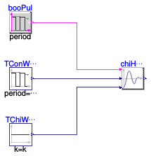
This example validates Buildings.Controls.OBC.ASHRAE.G36.Plants.Chillers.HeadPressure.Subsequences.ControlLoop. It demonstrates how the head pressure control loop signal is generated.
-
Before 0.5 seconds, the head pressure control loop is not enabled
(
uHeaPreEna=false). The loop output is not valid and will not be used. - At 0.5 seconds, the head pressure control loop is enabled. The PID controller resets the output from 0.
- From 0.5 seconds to 2.5 seconds, the difference between the condenser water return temperature and the chilled water supply temperature is 2 °K and it is less than the minimum LIFT (10 °K). The reverse acting PID controller gradually increases the output to 1.
- From 2.5 seconds to 4 seconds, the difference between the condenser water return temperature and the chilled water supply temperature is 13 °K and it is greater than the minimum LIFT (10 °K). The reverse acting PID controller gradually decreases the output to 0.
-
After 4 seconds, the head pressure control loop becomes disabled
(
uHeaPreEna=false). The loop output is not valid and will not be used.
Modelica definition
Buildings.Controls.OBC.ASHRAE.G36.Plants.Chillers.HeadPressure.Subsequences.Validation.MappingWithWSE
Validate sequence of specifying equipment setpoint based on head pressure control loop output
Information
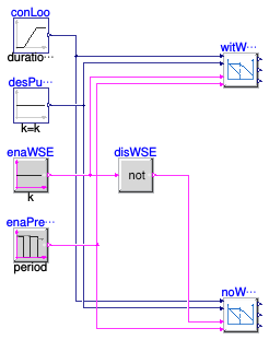
This example validates Buildings.Controls.OBC.ASHRAE.G36.Plants.Chillers.HeadPressure.Subsequences.MappingWithWSE. It demonstrates the setpoints control based on the output from the head pressure control loop.
The instances witWSE and noWSE show
the control when the waterside economizer is enabled and disabled
respectively.
-
In instance
withWSE, the economizer is enabled. Thus, the maximum tower speed setpoint and the condenser water pump speed setpoint are equal their maximum, which is 1. The head pressure control valve positionyHeaPreConValresets from 100% open at 0% loop output to minimum positionminHeaPreValPos(0.1) at 100% loop output. -
In instance
noWSE, the economizer is disabled.-
When the loop signal
uHeaPreConchanges from 0 to 50%, the maximum cooling tower speed setpointyMaxTowSpeSetresets from 100% to the minimum speedminTowSpe(0.1). -
When the loop signal
uHeaPreConchanges from 50% to 100%, the water pump speed setpointyConWatPumSpeSetresets from the stagedesConWatPumSpe(0.75) to the minimum speedminConWatPumSpe(0.1). - The head pressure control valve is fully open.
-
When the loop signal
- For both instances, when the head pressure control loop becomes disabled, the head pressure control valve is fully closed; the maximum tower speed setpoint and the condenser water pump speed setpoints become 0.
Modelica definition
Buildings.Controls.OBC.ASHRAE.G36.Plants.Chillers.HeadPressure.Subsequences.Validation.MappingWithoutWSE
Validate sequence of specifying equipment setpoint based on head pressure control loop output
Information
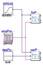
This example validates Buildings.Controls.OBC.ASHRAE.G36.Plants.Chillers.HeadPressure.Subsequences.MappingWithoutWSE. It demonstrates the setpoints control based on the output from the head pressure control loop.
The instances fixPumSpe and varPumSpe show
the control of the plants with the fixed speed condenser water pump
and the variable speed condenser water pump, respectively.
-
In instance
fixPumSpe, the condenser water pump speed is fixed.-
When the loop signal
uHeaPreConchanges from 0 to 50%, the maximum cooling tower speed setpointyMaxTowSpeSetresets from 100% to the minimum speedminTowSpe(0.1). -
When the loop signal
uHeaPreConchanges from 50% to 100%, the head pressure control valve setpointyHeaPreConValresets from 100% to the minimum positionminHeaPreValPos(0.1).
-
When the loop signal
-
In instance
varPumSpe, the condenser water pump speed is variable.-
When the loop signal
uHeaPreConchanges from 0 to 50%, the maximum cooling tower speed setpointyMaxTowSpeSetresets from 100% to the minimum speedminTowSpe(0.1). -
When the loop signal
uHeaPreConchanges from 50% to 100%, the condenser water pump speed setpointyConWatPumSpeSetresets from the design condenser water pump speeddesConWatPumSpeto the minimum speedminConWatPumSpe(0.1).
-
When the loop signal
- For both instances, when the head pressure control loop becomes disabled, the head pressure control valve is fully closed; the maximum tower speed setpoint and the condenser water pump speed setpoints become 0.