Package with control components for Buildings.Applications.DataCenters.ChillerCooled.Examples
Information
Collection of models for the control of chilled water system with waterside economizer.
Extends from Modelica.Icons.Package (Icon for standard packages).
Package Content
| Name |
Description |
 ChillerStage ChillerStage
|
Chiller staging control logic |
 ConstantSpeedPumpStage ConstantSpeedPumpStage
|
Staging control for constant speed pumps |
 CoolingMode CoolingMode
|
Mode controller for integrated waterside economizer and chiller |
 CoolingModeNonIntegrated CoolingModeNonIntegrated
|
Cooling mode controller in the chilled water system with a non-integrated waterside economizer |
 CoolingTowerSpeed CoolingTowerSpeed
|
Controller for the fan speed in cooling towers |
 Reheat Reheat
|
Model that implements an on and off controller for a reheater |
 Validation Validation
|
Collection of validation models |
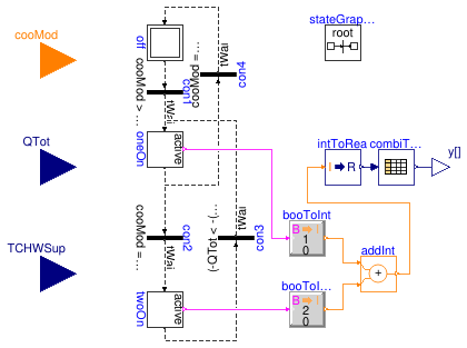
Chiller staging control logic
Information
This is a chiller staging control that works as follows:
-
The chillers are all off when cooling mode is Free Cooling.
-
One chiller is commanded on when cooling mode is not Free Cooling.
-
Two chillers are commanded on when cooling mode is not Free Cooling
and the cooling load addressed by each chiller is larger than
a critical value.
Extends from Modelica.Blocks.Icons.Block (Basic graphical layout of input/output block).
Parameters
| Type | Name | Default | Description |
|---|
| Time | tWai | | Waiting time [s] |
| Power | QEva_nominal | | Nominal cooling capaciaty(Negative means cooling) [W] |
| Power | criPoiLoa | 0.55*QEva_nominal | Critical point of cooling load for switching one chiller on or off [W] |
| Power | dQ | 0.25*QEva_nominal | Deadband for critical point of cooling load [W] |
| Temperature | criPoiTem | 279.15 | Critical point of temperature for switching one chiller on or off [K] |
| TemperatureDifference | dT | 1 | Deadband width for critical point of switching temperature [K] |
Connectors
| Type | Name | Description |
|---|
| input IntegerInput | cooMod | Cooling mode signal, integer value of
Buildings.Applications.DataCenters.Types.CoolingMode |
| input RealInput | QTot | Total cooling load in the chillers, negative |
| output RealOutput | y[2] | On/off signal for the chillers - 0: off; 1: on |
| input RealInput | TCHWSup | Temperature of leaving chilled water [K] |
Modelica definition
model ChillerStage
extends Modelica.Blocks.Icons.Block;
parameter Modelica.Units.SI.Time tWai ;
parameter Modelica.Units.SI.Power QEva_nominal
;
parameter Modelica.Units.SI.Power criPoiLoa=0.55*QEva_nominal
;
parameter Modelica.Units.SI.Power dQ=0.25*QEva_nominal
;
parameter Modelica.Units.SI.Temperature criPoiTem=279.15
;
parameter Modelica.Units.SI.TemperatureDifference dT=1
;
Modelica.Blocks.Interfaces.IntegerInput cooMod
;
Modelica.Blocks.Interfaces.RealInput QTot
;
Modelica.Blocks.Interfaces.RealOutput y[2]
;
Modelica.Blocks.Interfaces.RealInput TCHWSup(
final quantity="ThermodynamicTemperature",
final unit="K",
displayUnit="degC") ;
Modelica.StateGraph.Transition con1(
enableTimer=true,
waitTime=tWai,
condition=cooMod >
Integer(Buildings.Applications.DataCenters.Types.CoolingModes.FreeCooling))
;
Modelica.StateGraph.StepWithSignal oneOn(nIn=2, nOut=2)
;
Modelica.StateGraph.InitialStep off(nIn=1, nOut=1)
;
Modelica.StateGraph.StepWithSignal twoOn(nIn=1, nOut=1)
;
Modelica.StateGraph.Transition con2(
enableTimer=true,
waitTime=tWai,
condition=cooMod ==
Integer(Buildings.Applications.DataCenters.Types.CoolingModes.FullMechanical)
and
(-QTot > -(criPoiLoa + dQ)
or TCHWSup > criPoiTem + dT))
;
Modelica.StateGraph.Transition con3(
enableTimer=true,
waitTime=tWai,
condition=(-QTot < -(criPoiLoa - dQ)
or TCHWSup < criPoiTem - dT))
;
Modelica.StateGraph.Transition con4(
enableTimer=true,
waitTime=tWai,
condition=cooMod ==
Integer(Buildings.Applications.DataCenters.Types.CoolingModes.FreeCooling))
;
inner Modelica.StateGraph.StateGraphRoot stateGraphRoot;
Modelica.Blocks.Tables.CombiTable1Ds combiTable1Ds(
table=[0,0,0;
1,1,0;
2,1,1]);
Buildings.Controls.OBC.CDL.Conversions.BooleanToInteger booToInt(
final integerTrue=1,
final integerFalse=0);
Buildings.Controls.OBC.CDL.Conversions.BooleanToInteger booToInt1(
final integerFalse=0,
final integerTrue=2);
Buildings.Controls.OBC.CDL.Integers.Add addInt;
Buildings.Controls.OBC.CDL.Conversions.IntegerToReal intToRea;
equation
connect(off.outPort[1], con1.inPort);
connect(con1.outPort, oneOn.inPort[1]);
connect(con2.inPort, oneOn.outPort[1]);
connect(con2.outPort, twoOn.inPort[1]);
connect(twoOn.outPort[1], con3.inPort);
connect(con4.outPort, off.inPort[1]);
connect(con3.outPort, oneOn.inPort[2]);
connect(con4.inPort, oneOn.outPort[2]);
connect(combiTable1Ds.y, y);
connect(twoOn.active, booToInt1.u);
connect(oneOn.active, booToInt.u);
connect(booToInt.y, addInt.u1);
connect(booToInt1.y, addInt.u2);
connect(addInt.y, intToRea.u);
connect(intToRea.y, combiTable1Ds.u);
end ChillerStage;
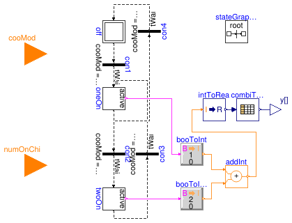
Staging control for constant speed pumps
Information
This model describes a simple staging control for two constant-speed pumps in
a chilled water plant with two chillers and a waterside economizer (WSE). The staging sequence
is shown as below.
-
When WSE is enabled, all the constant speed pumps are commanded on.
-
When fully mechanical cooling (FMC) mode is enabled, the number of running constant speed pumps
equals to the number of running chillers.
Extends from Modelica.Blocks.Icons.Block (Basic graphical layout of input/output block).
Parameters
| Type | Name | Default | Description |
|---|
| Time | tWai | | Waiting time [s] |
Connectors
| Type | Name | Description |
|---|
| input IntegerInput | cooMod | Cooling mode - 0:off, 1: free cooling mode; 2: partially mechanical cooling; 3: fully mechanical cooling |
| input BooleanInput | on | On signal of the plant |
| input IntegerInput | numOnChi | The number of running chillers |
| output RealOutput | y[2] | On/off signal - 0: off; 1: on |
Modelica definition
model ConstantSpeedPumpStage
extends Modelica.Blocks.Icons.Block;
parameter Modelica.Units.SI.Time tWai ;
Modelica.Blocks.Interfaces.IntegerInput cooMod
;
Modelica.Blocks.Interfaces.BooleanInput on
;
Modelica.Blocks.Interfaces.IntegerInput numOnChi
;
Modelica.Blocks.Interfaces.RealOutput y[2] ;
Modelica.StateGraph.Transition con1(
enableTimer=true,
waitTime=tWai,
condition=
cooMod ==
Integer(Buildings.Applications.DataCenters.Types.CoolingModes.FreeCooling)
or
cooMod ==
Integer(Buildings.Applications.DataCenters.Types.CoolingModes.PartialMechanical)
or
cooMod ==
Integer(Buildings.Applications.DataCenters.Types.CoolingModes.FullMechanical))
;
Modelica.StateGraph.StepWithSignal oneOn(nIn=2, nOut=2)
;
Modelica.StateGraph.InitialStep off(nIn=1, nOut=1)
;
Modelica.StateGraph.StepWithSignal twoOn(nIn=1, nOut=1)
;
Modelica.StateGraph.Transition con2(
enableTimer=true,
waitTime=tWai,
condition=
cooMod ==
Integer(Buildings.Applications.DataCenters.Types.CoolingModes.FreeCooling)
or
cooMod ==
Integer(Buildings.Applications.DataCenters.Types.CoolingModes.PartialMechanical)
or
(cooMod ==
Integer(Buildings.Applications.DataCenters.Types.CoolingModes.FullMechanical)
and numOnChi > 1))
;
Modelica.StateGraph.Transition con3(
enableTimer=true,
waitTime=tWai,
condition=cooMod ==
Integer(Buildings.Applications.DataCenters.Types.CoolingModes.FullMechanical)
and numOnChi < 2)
;
Modelica.StateGraph.Transition con4(
enableTimer=true,
waitTime=tWai,
condition=cooMod ==
Integer(Buildings.Applications.DataCenters.Types.CoolingModes.FreeCooling))
;
inner Modelica.StateGraph.StateGraphRoot stateGraphRoot;
Modelica.Blocks.Tables.CombiTable1Ds combiTable1Ds(table=[0,0,0; 1,1,0; 2,1,1]);
Buildings.Controls.OBC.CDL.Conversions.BooleanToInteger booToInt(
final integerTrue=1,
final integerFalse=0);
Buildings.Controls.OBC.CDL.Conversions.BooleanToInteger booToInt1(
final integerFalse=0,
final integerTrue=2);
Buildings.Controls.OBC.CDL.Integers.Add addInt;
Buildings.Controls.OBC.CDL.Conversions.IntegerToReal intToRea;
Buildings.Controls.OBC.CDL.Integers.Switch intSwi
;
Buildings.Controls.OBC.CDL.Integers.Sources.Constant zer(
final k=0)
;
equation
connect(off.outPort[1], con1.inPort);
connect(con1.outPort, oneOn.inPort[1]);
connect(con2.inPort, oneOn.outPort[1]);
connect(con2.outPort, twoOn.inPort[1]);
connect(twoOn.outPort[1], con3.inPort);
connect(con4.outPort, off.inPort[1]);
connect(con3.outPort, oneOn.inPort[2]);
connect(con4.inPort, oneOn.outPort[2]);
connect(combiTable1Ds.y, y);
connect(oneOn.active, booToInt.u);
connect(twoOn.active, booToInt1.u);
connect(booToInt.y, addInt.u1);
connect(booToInt1.y, addInt.u2);
connect(intToRea.y, combiTable1Ds.u);
connect(on, intSwi.u2);
connect(addInt.y, intSwi.u1);
connect(zer.y, intSwi.u3);
connect(intSwi.y, intToRea.u);
end ConstantSpeedPumpStage;
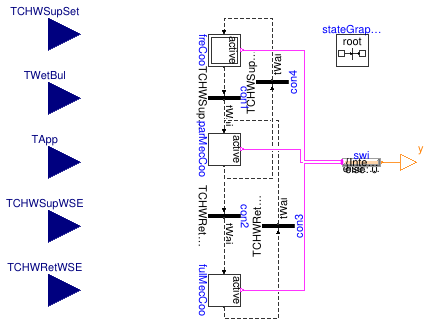
Mode controller for integrated waterside economizer and chiller
Information
Controller that outputs if the chilled water system is in Free Cooling (FC) mode,
Partially Mechanical Cooling (PMC) mode or Fully Mechanical Cooling (FMC) mode.
The waterside economizer is enabled when
-
The waterside economizer has been disabled for at least 20 minutes, and
-
TCHWR > TWetBul + TTowApp + deaBan1
The waterside economizer is disabled when
-
The waterside economizer has been enabled for at least 20 minutes, and
-
TWSE_CHWST > TWSE_CHWRT - deaBan2
The chiller is enabled when
-
The chiller has been disabled for at leat 20 minutes, and
-
TWSE_CHWST > TCHWSTSet + deaBan3
The chiller is disabled when
-
The chiller has been enabled for at leat 20 minutes, and
-
TWSE_CHWST ≤ TCHWSTSet + deaBan4
where TWSE_CHWST is the chilled water supply temperature for the WSE,
TWetBul is the wet bulb temperature,
TTowApp is the cooling tower approach, TWSE_CHWRT
is the chilled water return temperature for the WSE, and TCHWSTSet
is the chilled water supply temperature setpoint for the system.
deaBan 1-4 are deadbands for each switching point.
References
-
Stein, Jeff. Waterside Economizing in Data Centers: Design and Control Considerations.
ASHRAE Transactions 115.2 (2009).
Extends from Modelica.Blocks.Icons.Block (Basic graphical layout of input/output block).
Parameters
Connectors
| Type | Name | Description |
|---|
| input RealInput | TCHWRetWSE | Temperature of entering chilled water that flows to waterside economizer [K] |
| input RealInput | TCHWSupWSE | Temperature of leaving chilled water that flows out from waterside economizer [K] |
| input RealInput | TCHWSupSet | Supply chilled water temperature setpoint [K] |
| input RealInput | TApp | Approach temperature in the cooling tower [K] |
| output IntegerOutput | y | Cooling mode signal, integer value of Buildings.Applications.DataCenters.Types.CoolingMode |
| input RealInput | TWetBul | Wet bulb temperature of outdoor air [K] |
Modelica definition
model CoolingMode
extends Modelica.Blocks.Icons.Block;
parameter Modelica.Units.SI.Time tWai ;
parameter Modelica.Units.SI.TemperatureDifference deaBan1
;
parameter Modelica.Units.SI.TemperatureDifference deaBan2
;
parameter Modelica.Units.SI.TemperatureDifference deaBan3
;
parameter Modelica.Units.SI.TemperatureDifference deaBan4
;
Modelica.Blocks.Interfaces.RealInput TCHWRetWSE(
final quantity="ThermodynamicTemperature",
final unit="K",
displayUnit="degC")
;
Modelica.Blocks.Interfaces.RealInput TCHWSupWSE(
final quantity="ThermodynamicTemperature",
final unit="K",
displayUnit="degC")
;
Modelica.Blocks.Interfaces.RealInput TCHWSupSet(
final quantity="ThermodynamicTemperature",
final unit="K",
displayUnit="degC") ;
Modelica.Blocks.Interfaces.RealInput TApp(
final quantity="TemperatureDifference",
final unit="K",
displayUnit="degC") ;
Modelica.Blocks.Interfaces.IntegerOutput y
;
Modelica.StateGraph.Transition con1(
enableTimer=true,
waitTime=tWai,
condition=TCHWSupWSE > TCHWSupSet + deaBan1)
;
Modelica.StateGraph.StepWithSignal parMecCoo(nIn=2, nOut=2)
;
Modelica.StateGraph.InitialStepWithSignal freCoo(nIn=1, nOut=1)
;
Modelica.StateGraph.StepWithSignal fulMecCoo(nIn=1, nOut=1)
;
Modelica.StateGraph.Transition con2(
enableTimer=true,
waitTime=tWai,
condition=TCHWRetWSE < TCHWSupWSE + deaBan2)
;
Modelica.StateGraph.Transition con3(
enableTimer=true,
waitTime=tWai,
condition=TCHWRetWSE > TWetBul + TApp + deaBan3)
;
Modelica.StateGraph.Transition con4(
enableTimer=true,
waitTime=tWai,
condition=TCHWSupWSE <= TCHWSupSet + deaBan4)
;
inner Modelica.StateGraph.StateGraphRoot stateGraphRoot;
Modelica.Blocks.Interfaces.RealInput TWetBul(
final quantity="ThermodynamicTemperature",
final unit="K",
displayUnit="degC")
;
Modelica.Blocks.MathInteger.MultiSwitch swi(
y_default=0,
nu=3,
expr={
Integer(Buildings.Applications.DataCenters.Types.CoolingModes.FreeCooling),
Integer(Buildings.Applications.DataCenters.Types.CoolingModes.PartialMechanical),
Integer(Buildings.Applications.DataCenters.Types.CoolingModes.FullMechanical)})
;
equation
connect(freCoo.outPort[1], con1.inPort);
connect(con1.outPort, parMecCoo.inPort[1]);
connect(con2.inPort, parMecCoo.outPort[1]);
connect(con2.outPort, fulMecCoo.inPort[1]);
connect(fulMecCoo.outPort[1], con3.inPort);
connect(con4.outPort, freCoo.inPort[1]);
connect(con3.outPort, parMecCoo.inPort[2]);
connect(con4.inPort, parMecCoo.outPort[2]);
connect(swi.y, y);
connect(freCoo.active, swi.u[1]);
connect(parMecCoo.active, swi.u[2]);
connect(fulMecCoo.active, swi.u[3]);
end CoolingMode;
Cooling mode controller in the chilled water system with a non-integrated waterside economizer

Information
Chilled water plant with a non-integrated waterside economizer (WSE) have two cooling modes:
free cooling (FC) mode and fully mechanical cooling (FMC) mode. This model determines when to
activate FC or FMC for a chilled water system with 2 chillers and 1 waterside economizer.
The FMC mode is activated when
-
TWetBulb≥ TWetBulb,tran, or
-
TCHWST≥TCHWSTSet + deaBan,
and the FC mode is activated when
-
TWetBulb< TWetBulb,tran, and
-
numOnChi<2,
where TWetBulb is the wet bulb temperature of the outdoor air,
TWetBulb,tran is the wet bulb temperature transition point
for switching between FC and FMC,
TCHWST is the chilled water supply temperature, TCHWSTSet is
the chilled water supply temperature setpoint,and numOnChi is the number of running chillers.
Extends from Modelica.Blocks.Icons.Block (Basic graphical layout of input/output block).
Parameters
| Type | Name | Default | Description |
|---|
| TemperatureDifference | deaBan | | Dead band width for switching waterside economizer off [K] |
| Temperature | TSwi | | Temperature transition to free cooling mode [K] |
| Time | tWai | | Waiting time [s] |
Connectors
| Type | Name | Description |
|---|
| input IntegerInput | numOnChi | Number of running chillers |
| input RealInput | TWetBul | Wet bulb temperature of outdoor air [K] |
| input RealInput | TCHWSup | Temperature of leaving chilled water [K] |
| input RealInput | TCHWSupSet | Temperature setpoint of leaving chilled water [K] |
| output IntegerOutput | y | Cooling mode signal (1: free cooling mode, 3: fully mechanical cooling) |
Modelica definition
model CoolingModeNonIntegrated
extends Modelica.Blocks.Icons.Block;
parameter Modelica.Units.SI.TemperatureDifference deaBan
;
parameter Modelica.Units.SI.Temperature TSwi
;
parameter Modelica.Units.SI.Time tWai ;
Modelica.Blocks.Interfaces.IntegerInput numOnChi
;
Modelica.Blocks.Interfaces.RealInput TWetBul(
final quantity="ThermodynamicTemperature",
final unit="K",
displayUnit="degC")
;
Modelica.Blocks.Interfaces.RealInput TCHWSup(
final quantity="ThermodynamicTemperature",
final unit="K",
displayUnit="degC") ;
Modelica.Blocks.Interfaces.RealInput TCHWSupSet(
final quantity="ThermodynamicTemperature",
final unit="K",
displayUnit="degC") ;
Modelica.Blocks.Interfaces.IntegerOutput y
;
Modelica.StateGraph.InitialStepWithSignal freCoo(nIn=1, nOut=1)
;
Modelica.StateGraph.StepWithSignal fulMecCoo(nIn=1, nOut=1)
;
Modelica.StateGraph.Transition con1(
enableTimer=true,
waitTime=tWai,
condition=TWetBul > TSwi + deaBan
or TCHWSup > TCHWSupSet + deaBan)
;
Modelica.Blocks.MathInteger.MultiSwitch swi(
nu=2,
y_default=0,
expr={
Integer(Buildings.Applications.DataCenters.Types.CoolingModes.FreeCooling),
Integer(Buildings.Applications.DataCenters.Types.CoolingModes.FullMechanical)})
;
Modelica.StateGraph.Transition con2(
enableTimer=true,
waitTime=tWai,
condition=TWetBul <= TSwi - deaBan
and numOnChi == 1)
;
inner Modelica.StateGraph.StateGraphRoot stateGraphRoot;
equation
connect(freCoo.outPort[1],con1. inPort);
connect(con1.outPort,fulMecCoo. inPort[1]);
connect(fulMecCoo.outPort[1], con2.inPort);
connect(con2.outPort, freCoo.inPort[1]);
connect(freCoo.active, swi.u[1]);
connect(fulMecCoo.active, swi.u[2]);
connect(swi.y, y);
end CoolingModeNonIntegrated;
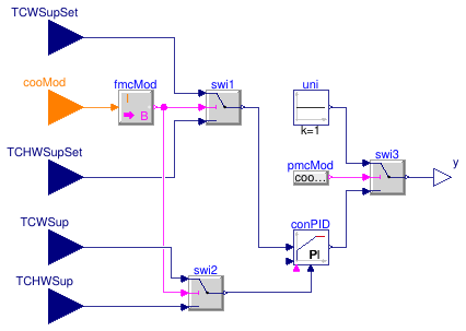
Controller for the fan speed in cooling towers
Information
This model describes a simple cooling tower speed controller for
a chilled water system with integrated waterside economizers.
The control logics are described in the following:
- When the system is in Fully Mechanical Cooling (FMC) mode,
the cooling tower fan speed is controlled to maintain the condener water supply temperature (CWST)
at or around the setpoint.
- When the system is in Partially Mechanical Cooling (PMC) mode,
the cooling tower fan speed is set as 100% to make condenser water
as cold as possible and maximize the waterside economzier output.
- When the system is in Free Cooling (FC) mode,
the cooling tower fan speed is controlled to maintain the chilled water supply temperature (CHWST)
at or around its setpoint.
Extends from Modelica.Blocks.Icons.Block (Basic graphical layout of input/output block).
Parameters
| Type | Name | Default | Description |
|---|
| Controller |
| SimpleController | controllerType | Modelica.Blocks.Types.Simple... | Type of controller |
| Real | k | 1 | Gain of controller [1] |
| Time | Ti | 0.5 | Time constant of integrator block [s] |
| Time | Td | 0.1 | Time constant of derivative block [s] |
| Real | yMax | 1 | Upper limit of output |
| Real | yMin | 0 | Lower limit of output |
| Boolean | reverseActing | false | Set to true for throttling the water flow rate through a cooling coil controller |
Connectors
| Type | Name | Description |
|---|
| input RealInput | TCHWSupSet | Chilled water supply temperature setpoint [K] |
| input RealInput | TCWSupSet | Condenser water supply temperature setpoint [K] |
| input RealInput | TCHWSup | Chilled water supply temperature [K] |
| input RealInput | TCWSup | Condenser water supply temperature [K] |
| output RealOutput | y | Speed signal for cooling tower fans |
| input IntegerInput | cooMod | Cooling mode signal, integer value of
Buildings.Applications.DataCenters.Types.CoolingMode |
Modelica definition
model CoolingTowerSpeed
extends Modelica.Blocks.Icons.Block;
parameter Modelica.Blocks.Types.SimpleController controllerType=
Modelica.Blocks.Types.SimpleController.PI
;
parameter Real k(min=0, unit="1") = 1
;
parameter Modelica.Units.SI.Time Ti(min=Modelica.Constants.small) = 0.5
;
parameter Modelica.Units.SI.Time Td(min=0) = 0.1
;
parameter Real yMax(start=1)=1
;
parameter Real yMin=0
;
parameter Boolean reverseActing=false
;
Modelica.Blocks.Interfaces.RealInput TCHWSupSet(
final quantity="ThermodynamicTemperature",
final unit="K",
displayUnit="degC") ;
Modelica.Blocks.Interfaces.RealInput TCWSupSet(
final quantity="ThermodynamicTemperature",
final unit="K",
displayUnit="degC") ;
Modelica.Blocks.Interfaces.RealInput TCHWSup(
final quantity="ThermodynamicTemperature",
final unit="K",
displayUnit="degC") ;
Modelica.Blocks.Interfaces.RealInput TCWSup(
final quantity="ThermodynamicTemperature",
final unit="K",
displayUnit="degC") ;
Modelica.Blocks.Interfaces.RealOutput y
;
Modelica.Blocks.Sources.Constant uni(k=1) ;
Modelica.Blocks.Sources.BooleanExpression pmcMod(
y= cooMod ==
Integer(Buildings.Applications.DataCenters.Types.CoolingModes.PartialMechanical))
;
Modelica.Blocks.Interfaces.IntegerInput cooMod
;
Buildings.Controls.Continuous.LimPID conPID(
controllerType=controllerType,
k=k,
Ti=Ti,
Td=Td,
yMax=yMax,
yMin=yMin,
reverseActing=reverseActing)
;
Modelica.Blocks.Math.IntegerToBoolean fmcMod(threshold=3)
;
protected
Modelica.Blocks.Logical.Switch swi1
;
Modelica.Blocks.Logical.Switch swi2
;
Modelica.Blocks.Logical.Switch swi3
;
equation
connect(TCWSupSet, swi1.u1);
connect(TCHWSupSet, swi1.u3);
connect(swi1.y, conPID.u_s);
connect(fmcMod.y, swi2.u2);
connect(TCWSup, swi2.u1);
connect(TCHWSup, swi2.u3);
connect(swi2.y, conPID.u_m);
connect(pmcMod.y, swi3.u2);
connect(uni.y, swi3.u1);
connect(conPID.y, swi3.u3);
connect(swi3.y, y);
connect(fmcMod.y, swi1.u2);
connect(cooMod, fmcMod.u);
end CoolingTowerSpeed;
Model that implements an on and off controller for a reheater
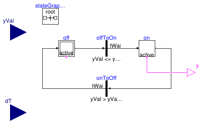
Information
This model can be used to generate on/off signal for the reheater inside the AHU.
This reheater will be on only if the following two conditions are satisfied at the same time:
- The position of the water-side valve reaches its switch point,
yValSwi;
- The difference between the inlet temperature of the reheater and the required outlet temperature setpoint
is lower than its critical switch point,
dTSwi.
In addition, a deadband and waiting time is used to avoid frequent switching.
Parameters
| Type | Name | Default | Description |
|---|
| Real | yValSwi | | Switch point for valve signal [1] |
| Real | yValDeaBan | | Deadband for valve signal [1] |
| TemperatureDifference | dTSwi | | Switch point for temperature difference [K] |
| TemperatureDifference | dTDeaBan | | Deadband for temperature difference [K] |
| Time | tWai | | Waiting time [s] |
Connectors
| Type | Name | Description |
|---|
| input RealInput | yVal | Valve position [1] |
| input RealInput | dT | Temperature difference [K] |
| output BooleanOutput | y | On and off signal for the reheater |
Modelica definition
model Reheat
parameter Real yValSwi(min=0, max=1, unit="1")
;
parameter Real yValDeaBan(min=0, max=1, unit="1")
;
parameter Modelica.Units.SI.TemperatureDifference dTSwi
;
parameter Modelica.Units.SI.TemperatureDifference dTDeaBan
;
parameter Modelica.Units.SI.Time tWai ;
Modelica.Blocks.Interfaces.RealInput yVal(
min=0,
max=1,
unit="1") ;
Modelica.Blocks.Interfaces.RealInput dT(
final quantity="ThermodynamicTemperature",
final unit="K")
;
Modelica.Blocks.Interfaces.BooleanOutput y
;
Modelica.StateGraph.InitialStepWithSignal off(nIn=1, nOut=1)
;
Modelica.StateGraph.StepWithSignal on(nIn=1, nOut=1)
;
Modelica.StateGraph.Transition offToOn(
enableTimer=true,
waitTime=tWai,
condition=yVal <= yValSwi - yValDeaBan
and dT < dTSwi - dTDeaBan)
;
Modelica.StateGraph.Transition onToOff(
condition=yVal > yValSwi+yValDeaBan
or dT > dTSwi+dTDeaBan,
enableTimer=true,
waitTime=tWai)
;
inner Modelica.StateGraph.StateGraphRoot stateGraphRoot;
equation
connect(off.outPort[1], offToOn.inPort);
connect(offToOn.outPort, on.inPort[1]);
connect(on.outPort[1], onToOff.inPort);
connect(onToOff.outPort, off.inPort[1]);
connect(on.active, y);
end Reheat;
 Buildings.Applications.DataCenters.ChillerCooled.Controls.ChillerStage
 Buildings.Applications.DataCenters.ChillerCooled.Controls.ConstantSpeedPumpStage
 Buildings.Applications.DataCenters.ChillerCooled.Controls.CoolingMode
 Buildings.Applications.DataCenters.ChillerCooled.Controls.CoolingModeNonIntegrated
 Buildings.Applications.DataCenters.ChillerCooled.Controls.CoolingTowerSpeed
 Buildings.Applications.DataCenters.ChillerCooled.Controls.Reheat