This package contains examples that demonstrate the usage of the components of the Electrical.Analog library.
The examples are simple to understand. They will show a typical behavior of the components, and they will give hints to users.
Extends from Modelica.Icons.ExamplesPackage (Icon for packages containing runnable examples).
| Name | Description |
|---|---|
| Cauer low pass filter with analog components | |
| Cauer low pass filter with operational amplifiers | |
| Cauer low-pass filter with operational amplifiers and switched capacitors | |
| Characteristic of ideal diodes | |
| Characteristic of ideal thyristors | |
| Chua's circuit, ns, V, A | |
| Simple NPN transistor amplifier circuit | |
| Heating MOS Inverter | |
| Heating NPN Or Gate | |
| Heating resistor | |
| Heating rectifier | |
| CMOS NAND Gate (see Tietze/Schenk, page 157) | |
| Example for Zener diodes | |
| B6 diode bridge | |
| Simple demo to show behaviour of SaturatingInductor component | |
| Simple demo of a VariableResistor model | |
| Comparison of switch models both with and without arc | |
| Thyristor demonstration example | |
| Simple Amplifier circuit which uses OpAmpDetailed | |
| Transformer circuit to show the magnetization facilities | |
| Comparison of controlled switch models both with and without arc | |
| Simple triac test circuit | |
| Ideal triac test circuit | |
| Conversion circuit | |
| Utility components used by package Examples |
 Modelica.Electrical.Analog.Examples.CauerLowPassAnalog
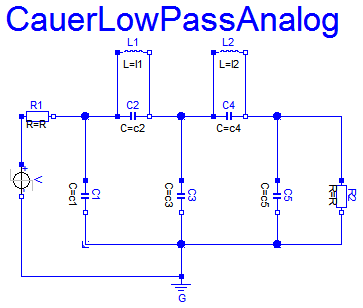
The example Cauer Filter is a low-pass-filter of the fifth order. It is realized using an analog network. The voltage source V is the input voltage (step), and the R2.p.v is the filter output voltage. The pulse response is calculated.
The simulation end time should be 60. Please plot both V.p.v (input voltage) and R2.p.v (output voltage).
Extends from Modelica.Icons.Example (Icon for runnable examples).
| Type | Name | Default | Description |
|---|---|---|---|
| Inductance | l1 | 1.304 | filter coefficient I1 [H] |
| Inductance | l2 | 0.8586 | filter coefficient I2 [H] |
| Capacitance | c1 | 1.072 | filter coefficient c1 [F] |
| Capacitance | c2 | 1/(1.704992^2*l1) | filter coefficient c2 [F] |
| Capacitance | c3 | 1.682 | filter coefficient c3 [F] |
| Capacitance | c4 | 1/(1.179945^2*l2) | filter coefficient c4 [F] |
| Capacitance | c5 | 0.7262 | filter coefficient c5 [F] |
model CauerLowPassAnalog
  "Cauer low pass filter with analog components"
  extends Modelica.Icons.Example;

  parameter Modelica.SIunits.Inductance l1=1.304 "filter coefficient I1";
  parameter Modelica.SIunits.Inductance l2=0.8586 "filter coefficient I2";
  parameter Modelica.SIunits.Capacitance c1=1.072 "filter coefficient c1";
  parameter Modelica.SIunits.Capacitance c2=1/(1.704992^2*l1)
    "filter coefficient c2";
  parameter Modelica.SIunits.Capacitance c3=1.682 "filter coefficient c3";
  parameter Modelica.SIunits.Capacitance c4=1/(1.179945^2*l2)
    "filter coefficient c4";
  parameter Modelica.SIunits.Capacitance c5=0.7262 "filter coefficient c5";
  Modelica.Electrical.Analog.Basic.Ground G;
  Modelica.Electrical.Analog.Basic.Capacitor C1(C=c1);
  Modelica.Electrical.Analog.Basic.Capacitor C2(C=c2);
  Modelica.Electrical.Analog.Basic.Capacitor C3(C=c3);
  Modelica.Electrical.Analog.Basic.Capacitor C4(C=c4);
  Modelica.Electrical.Analog.Basic.Capacitor C5(C=c5);
  Modelica.Electrical.Analog.Basic.Inductor L1(L=l1);
  Modelica.Electrical.Analog.Basic.Inductor L2(L=l2);
  Modelica.Electrical.Analog.Basic.Resistor R1;
  Modelica.Electrical.Analog.Basic.Resistor R2;
  Modelica.Electrical.Analog.Sources.StepVoltage V(startTime=1, offset=0);
equation
  connect(R1.n,C1. p);
  connect(C1.n,G. p);
  connect(R1.n,C2. p);
  connect(L1.p,C2. p);
  connect(L1.p,C1. p);
  connect(L1.n,C2. n);
  connect(C2.n,C3. p);
  connect(C2.n,C4. p);
  connect(L1.n,C3. p);
  connect(L1.n,C4. p);
  connect(L2.p,C4. p);
  connect(C2.n,L2. p);
  connect(C3.p,L2. p);
  connect(L2.n,C4. n);
  connect(L2.n,C5. p);
  connect(L2.n,R2. p);
  connect(R2.n,G. p);
  connect(C4.n,C5. p);
  connect(C4.n,R2. p);
  connect(C3.n,G. p);
  connect(C5.n,G. p);
  connect(C1.n,C3. n);
  connect(C1.n,C5. n);
  connect(R2.n,C5. n);
  connect(R2.n,C3. n);
  connect(R2.n,C1. n);
  connect(C5.p,R2. p);
  connect(R1.p, V.p);
  connect(V.n, G.p);
end CauerLowPassAnalog;
 Modelica.Electrical.Analog.Examples.CauerLowPassOPV
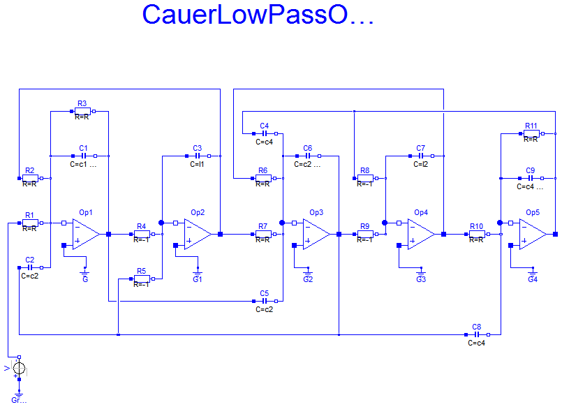
The example Cauer Filter is a low-pass-filter of the fifth order. It is realized using an analog network with operational amplifiers. The voltage source V is the input voltage (step), and the OP5.out.v is the filter output voltage. The pulse response is calculated.
This model is identical to the CauerLowPassAnalog example, but inverting. To get the same response as that of the CauerLowPassAnalog example, a negative voltage step is used as input.
The simulation end time should be 60. Please plot both V.v (which is the inverted input voltage) and OP5.p.v (output voltage). Compare this result with the CauerLowPassAnalog result.
During translation some warnings are issued concerning resistor values (Value=-1 not in range[0,1.e+100]). Do not worry about it. The negative values are o.k.
Extends from Modelica.Icons.Example (Icon for runnable examples).
| Type | Name | Default | Description |
|---|---|---|---|
| Capacitance | l1 | 1.304 | filter coefficient i1 [F] |
| Capacitance | l2 | 0.8586 | filter coefficient i2 [F] |
| Capacitance | c1 | 1.072 | filter coefficient c1 [F] |
| Capacitance | c2 | 1/(1.704992^2*l1) | filter coefficient c2 [F] |
| Capacitance | c3 | 1.682 | filter coefficient c3 [F] |
| Capacitance | c4 | 1/(1.179945^2*l2) | filter coefficient c4 [F] |
| Capacitance | c5 | 0.7262 | filter coefficient c5 [F] |
model CauerLowPassOPV
  "Cauer low pass filter with operational amplifiers"
  extends Modelica.Icons.Example;

  parameter Modelica.SIunits.Capacitance l1=1.304 "filter coefficient i1";
  parameter Modelica.SIunits.Capacitance l2=0.8586 "filter coefficient i2";
  parameter Modelica.SIunits.Capacitance c1=1.072 "filter coefficient c1";
  parameter Modelica.SIunits.Capacitance c2=1/(1.704992^2*l1)
    "filter coefficient c2";
  parameter Modelica.SIunits.Capacitance c3=1.682 "filter coefficient c3";
  parameter Modelica.SIunits.Capacitance c4=1/(1.179945^2*l2)
    "filter coefficient c4";
  parameter Modelica.SIunits.Capacitance c5=0.7262 "filter coefficient c5";
  Modelica.Electrical.Analog.Basic.Capacitor C1(C=c1 + c2);
  Modelica.Electrical.Analog.Basic.Capacitor C2(C=c2);
  Modelica.Electrical.Analog.Basic.Capacitor C3(C=l1);
  Modelica.Electrical.Analog.Basic.Capacitor C4(C=c4);
  Modelica.Electrical.Analog.Basic.Capacitor C5(C=c2);
  Modelica.Electrical.Analog.Basic.Resistor R1;
  Modelica.Electrical.Analog.Basic.Resistor R2;
  Modelica.Electrical.Analog.Basic.Resistor R3;
  Modelica.Electrical.Analog.Ideal.IdealOpAmp3Pin Op1;
  Modelica.Electrical.Analog.Basic.Ground G;
  Modelica.Electrical.Analog.Basic.Resistor R4(R=-1);
  Modelica.Electrical.Analog.Basic.Resistor R5(R=-1);
  Modelica.Electrical.Analog.Ideal.IdealOpAmp3Pin Op2;
  Modelica.Electrical.Analog.Ideal.IdealOpAmp3Pin Op3;
  Modelica.Electrical.Analog.Basic.Ground G1;
  Modelica.Electrical.Analog.Basic.Resistor R6;
  Modelica.Electrical.Analog.Basic.Resistor R7;
  Modelica.Electrical.Analog.Basic.Capacitor C6(C=c2 + c3 + c4);
  Modelica.Electrical.Analog.Basic.Resistor R8(R=-1);
  Modelica.Electrical.Analog.Basic.Resistor R9(R=-1);
  Modelica.Electrical.Analog.Basic.Resistor R10;
  Modelica.Electrical.Analog.Ideal.IdealOpAmp3Pin Op4;
  Modelica.Electrical.Analog.Ideal.IdealOpAmp3Pin Op5;
  Modelica.Electrical.Analog.Basic.Capacitor C7(C=l2);
  Modelica.Electrical.Analog.Basic.Capacitor C8(C=c4);
  Modelica.Electrical.Analog.Basic.Capacitor C9(C=c4 + c5);
  Modelica.Electrical.Analog.Basic.Resistor R11;
protected
  Modelica.Electrical.Analog.Interfaces.NegativePin n1;
protected
  Modelica.Electrical.Analog.Interfaces.NegativePin n2;
protected
  Modelica.Electrical.Analog.Interfaces.NegativePin n3;
protected
  Modelica.Electrical.Analog.Interfaces.NegativePin n4;
protected
  Modelica.Electrical.Analog.Interfaces.NegativePin n5;
protected
  Modelica.Electrical.Analog.Interfaces.PositivePin p1;
protected
  Modelica.Electrical.Analog.Interfaces.NegativePin n6;
protected
  Modelica.Electrical.Analog.Interfaces.NegativePin n7;
protected
  Modelica.Electrical.Analog.Interfaces.NegativePin n8;
protected
  Modelica.Electrical.Analog.Interfaces.PositivePin p2;
protected
  Modelica.Electrical.Analog.Interfaces.PositivePin out1;
protected
  Modelica.Electrical.Analog.Interfaces.PositivePin p3;
protected
  Modelica.Electrical.Analog.Interfaces.NegativePin n9;
protected
  Modelica.Electrical.Analog.Interfaces.NegativePin n10;
protected
  Modelica.Electrical.Analog.Interfaces.NegativePin n11;
public
  Modelica.Electrical.Analog.Basic.Ground G2;
protected
  Modelica.Electrical.Analog.Interfaces.NegativePin n12;
protected
  Modelica.Electrical.Analog.Interfaces.NegativePin n13;
protected
  Modelica.Electrical.Analog.Interfaces.PositivePin p4;
protected
  Modelica.Electrical.Analog.Interfaces.NegativePin n14;
public
  Modelica.Electrical.Analog.Basic.Ground G3;
  Modelica.Electrical.Analog.Basic.Ground G4;
  Modelica.Electrical.Analog.Sources.StepVoltage V(startTime=1);
  Modelica.Electrical.Analog.Basic.Ground Ground1;
equation
  connect(Op1.in_p, G.p);
  connect(G1.p, Op2.in_p);
  connect(R1.n, n1);
  connect(n1, Op1.in_n);
  connect(C2.n, n1);
  connect(R2.n, n2);
  connect(n1, n2);
  connect(n2, n3);
  connect(n3, C1.p);
  connect(n3, R3.p);
  connect(C1.n, n4);
  connect(R3.n, n4);
  connect(n4, Op1.out);
  connect(R4.p, Op1.out);
  connect(C5.p, Op1.out);
  connect(R4.n, n5);
  connect(n5, Op2.in_n);
  connect(C3.p, n5);
  connect(R5.n, n5);
  connect(R5.p, p1);
  connect(C2.p, p1);
  connect(C3.n, n6);
  connect(n6, Op2.out);
  connect(R2.p, n6);
  connect(Op2.out, R7.p);
  connect(R7.n, n7);
  connect(n7, Op3.in_n);
  connect(C5.n, n7);
  connect(R6.n, n8);
  connect(n7, n8);
  connect(C6.p, p2);
  connect(n8, p2);
  connect(C4.n, p2);
  connect(C6.n, Op3.out);
  connect(R9.p, Op3.out);
  connect(Op3.out, out1);
  connect(p1, out1);
  connect(out1, C8.p);
  connect(C4.p, p3);
  connect(p3, R8.p);
  connect(R8.n, n9);
  connect(n9, n10);
  connect(R9.n, n10);
  connect(n10, Op4.in_n);
  connect(n9, C7.p);
  connect(C7.n, n11);
  connect(R6.p, n11);
  connect(n11, Op4.out);
  connect(Op4.out, R10.p);
  connect(G2.p, Op3.in_p);
  connect(R11.n, n12);
  connect(p3, n12);
  connect(C9.n, n13);
  connect(n12, n13);
  connect(n13, Op5.out);
  connect(C9.p, p4);
  connect(R11.p, p4);
  connect(R10.n, n14);
  connect(p4, n14);
  connect(Op5.in_n, n14);
  connect(C8.n, n14);
  connect(Op4.in_p, G3.p);
  connect(Op5.in_p, G4.p);
  connect(V.p, Ground1.p);
  connect(V.n, R1.p);
end CauerLowPassOPV;
Modelica.Electrical.Analog.Examples.CauerLowPassSC
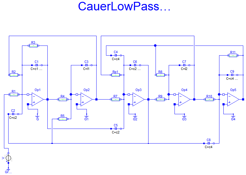
The example CauerLowPassSC is a low-pass-filter of the fifth order. It is realized using an switched-capacitor network with operational amplifiers. The voltage source V is the input voltage (step), and the OP5.out.v is the filter output voltage. The pulse response is calculated.
This model is identical to the CauerLowPassAnalog example, but inverting. To get the same response as that of the CauerLowPassAnalog example, a negative voltage step is used as input.
This model is identical to the CauerLowPassOPV example. But the resistors are realized by switched capacitors. There are two such resistors Rp (of value +1), and Rn (of value -1). In this models the switching clock source is included. In a typical switched capacitor circuit there would be a central clock source.
The simulation end time should be 60. Please plot both V.v (which is the inverted input voltage) and OP5.p.v (output voltage). Compare this result with the CauerLowPassAnalog result.
Due to the recharging of the capacitances after switching the performance of simulation is not as good as in the CauerLowPassOPV example.
Extends from Modelica.Icons.Example (Icon for runnable examples).
| Type | Name | Default | Description |
|---|---|---|---|
| Capacitance | l1 | 1.304 | filter coefficient i1 [F] |
| Capacitance | l2 | 0.8586 | filter coefficient i2 [F] |
| Capacitance | c1 | 1.072 | filter coefficient c1 [F] |
| Capacitance | c2 | 1/(1.704992^2*l1) | filter coefficient c2 [F] |
| Capacitance | c3 | 1.682 | filter coefficient c3 [F] |
| Capacitance | c4 | 1/(1.179945^2*l2) | filter coefficient c4 [F] |
| Capacitance | c5 | 0.7262 | filter coefficient c5 [F] |
model CauerLowPassSC "Cauer low-pass filter with operational amplifiers and switched capacitors" extends Modelica.Icons.Example;model Rn "Negative resistance" parameter Modelica.SIunits.Time clock=1 "Clock"; parameter Modelica.SIunits.Resistance R(min=Modelica.Constants.eps)=1 "Resistance"; Modelica.Blocks.Sources.BooleanPulse BooleanPulse1(period=clock); Modelica.Electrical.Analog.Basic.Capacitor Capacitor1(C=clock/R); Modelica.Electrical.Analog.Ideal.IdealCommutingSwitch IdealCommutingSwitch1; Modelica.Electrical.Analog.Ideal.IdealCommutingSwitch IdealCommutingSwitch2; Modelica.Electrical.Analog.Basic.Ground Ground1; Modelica.Electrical.Analog.Basic.Ground Ground2; Modelica.Electrical.Analog.Interfaces.NegativePin n1; Modelica.Electrical.Analog.Interfaces.NegativePin n2; equationconnect(IdealCommutingSwitch1.p,Capacitor1. p); connect(Capacitor1.n,IdealCommutingSwitch2. p); connect(IdealCommutingSwitch2.control,BooleanPulse1. y); connect(IdealCommutingSwitch1.control,BooleanPulse1. y); connect(Ground2.p,IdealCommutingSwitch2. n2); connect(IdealCommutingSwitch2.n1,n2); connect(n1, IdealCommutingSwitch1.n2); connect(Ground1.p, IdealCommutingSwitch1.n1); end Rn ;model Rp "Positive resistance" parameter Modelica.SIunits.Time clock=1 "Clock"; parameter Modelica.SIunits.Resistance R(min=Modelica.Constants.eps)=1 "Resistance"; Modelica.Blocks.Sources.BooleanPulse BooleanPulse1(period=clock); Modelica.Electrical.Analog.Basic.Capacitor Capacitor1(C=clock/R); Modelica.Electrical.Analog.Ideal.IdealCommutingSwitch IdealCommutingSwitch1; Modelica.Electrical.Analog.Ideal.IdealCommutingSwitch IdealCommutingSwitch2; Modelica.Electrical.Analog.Basic.Ground Ground1; Modelica.Electrical.Analog.Basic.Ground Ground2; Modelica.Electrical.Analog.Interfaces.NegativePin n1; Modelica.Electrical.Analog.Interfaces.NegativePin n2; equationconnect(IdealCommutingSwitch1.p, Capacitor1.p); connect(Capacitor1.n, IdealCommutingSwitch2.p); connect(IdealCommutingSwitch2.control, BooleanPulse1.y); connect(IdealCommutingSwitch1.control, BooleanPulse1.y); connect(Ground1.p, IdealCommutingSwitch1.n2); connect(Ground2.p, IdealCommutingSwitch2.n2); connect(IdealCommutingSwitch1.n1, n1); connect(IdealCommutingSwitch2.n1, n2); end Rp ; parameter Modelica.SIunits.Capacitance l1=1.304 "filter coefficient i1"; parameter Modelica.SIunits.Capacitance l2=0.8586 "filter coefficient i2"; parameter Modelica.SIunits.Capacitance c1=1.072 "filter coefficient c1"; parameter Modelica.SIunits.Capacitance c2=1/(1.704992^2*l1) "filter coefficient c2"; parameter Modelica.SIunits.Capacitance c3=1.682 "filter coefficient c3"; parameter Modelica.SIunits.Capacitance c4=1/(1.179945^2*l2) "filter coefficient c4"; parameter Modelica.SIunits.Capacitance c5=0.7262 "filter coefficient c5";Modelica.Electrical.Analog.Basic.Capacitor C1(C=c1 + c2); Modelica.Electrical.Analog.Basic.Capacitor C2(C=c2); Modelica.Electrical.Analog.Basic.Capacitor C3(C=l1); Modelica.Electrical.Analog.Basic.Capacitor C4(C=c4); Modelica.Electrical.Analog.Basic.Capacitor C5(C=c2); Modelica.Electrical.Analog.Ideal.IdealOpAmp3Pin Op1; Modelica.Electrical.Analog.Basic.Ground G; Modelica.Electrical.Analog.Ideal.IdealOpAmp3Pin Op2; Modelica.Electrical.Analog.Ideal.IdealOpAmp3Pin Op3; Modelica.Electrical.Analog.Basic.Ground G1; Modelica.Electrical.Analog.Basic.Capacitor C6(C=c2 + c3 + c4); Modelica.Electrical.Analog.Ideal.IdealOpAmp3Pin Op4; Modelica.Electrical.Analog.Ideal.IdealOpAmp3Pin Op5; Modelica.Electrical.Analog.Basic.Capacitor C7(C=l2); Modelica.Electrical.Analog.Basic.Capacitor C8(C=c4); Modelica.Electrical.Analog.Basic.Capacitor C9(C=c4 + c5); protected Modelica.Electrical.Analog.Interfaces.NegativePin n1; protected Modelica.Electrical.Analog.Interfaces.NegativePin n2; protected Modelica.Electrical.Analog.Interfaces.NegativePin n3; protected Modelica.Electrical.Analog.Interfaces.NegativePin n4; protected Modelica.Electrical.Analog.Interfaces.NegativePin n5; protected Modelica.Electrical.Analog.Interfaces.PositivePin p1; protected Modelica.Electrical.Analog.Interfaces.NegativePin n6; protected Modelica.Electrical.Analog.Interfaces.NegativePin n7; protected Modelica.Electrical.Analog.Interfaces.NegativePin n8; protected Modelica.Electrical.Analog.Interfaces.PositivePin p2; protected Modelica.Electrical.Analog.Interfaces.PositivePin out1; protected Modelica.Electrical.Analog.Interfaces.PositivePin p3; protected Modelica.Electrical.Analog.Interfaces.NegativePin n9; protected Modelica.Electrical.Analog.Interfaces.NegativePin n10; protected Modelica.Electrical.Analog.Interfaces.NegativePin n11; public Modelica.Electrical.Analog.Basic.Ground G2; protected Modelica.Electrical.Analog.Interfaces.NegativePin n12; protected Modelica.Electrical.Analog.Interfaces.NegativePin n13; protected Modelica.Electrical.Analog.Interfaces.PositivePin p4; protected Modelica.Electrical.Analog.Interfaces.NegativePin n14; public Modelica.Electrical.Analog.Basic.Ground G3; Modelica.Electrical.Analog.Basic.Ground G4; Modelica.Electrical.Analog.Sources.StepVoltage V(startTime=1); Modelica.Electrical.Analog.Basic.Ground Ground1; Rn R4(clock=0.1); Rn R5(clock=0.1); Rn R8(clock=0.1); Rn R9(clock=0.1); Rp R1(clock=0.1); Rp R2(clock=0.1); Rp R3(clock=0.1); Rp Rp1(clock=0.1); Rp R7(clock=0.1); Rp R10(clock=0.1); Rp R11(clock=0.1); equationconnect(Op1.in_p,G. p); connect(G1.p,Op2. in_p); connect(n1,Op1. in_n); connect(C2.n,n1); connect(n1,n2); connect(n2,n3); connect(n3,C1. p); connect(C1.n,n4); connect(n4,Op1. out); connect(C5.p,Op1. out); connect(n5,Op2. in_n); connect(C3.p,n5); connect(C2.p,p1); connect(C3.n,n6); connect(n6,Op2. out); connect(n7,Op3. in_n); connect(C5.n,n7); connect(n7,n8); connect(C6.p,p2); connect(n8,p2); connect(C4.n,p2); connect(C6.n,Op3. out); connect(Op3.out,out1); connect(p1,out1); connect(out1,C8. p); connect(C4.p,p3); connect(n9,n10); connect(n10,Op4. in_n); connect(n9,C7. p); connect(C7.n,n11); connect(n11,Op4. out); connect(G2.p,Op3. in_p); connect(p3,n12); connect(C9.n,n13); connect(n12,n13); connect(n13,Op5. out); connect(C9.p,p4); connect(p4,n14); connect(Op5.in_n,n14); connect(C8.n,n14); connect(Op4.in_p,G3. p); connect(Op5.in_p,G4. p); connect(V.p, Ground1.p); connect(R4.n2, n5); connect(Op1.out, R4.n1); connect(R5.n1, p1); connect(R5.n2, n5); connect(p3, R8.n1); connect(R8.n2, n9); connect(Op3.out, R9.n1); connect(R9.n2, n10); connect(R1.n1, V.n); connect(R1.n2, n1); connect(R2.n2, n2); connect(R2.n1, n6); connect(R3.n1, n3); connect(R3.n2, n4); connect(Rp1.n2, n8); connect(Rp1.n1, n11); connect(Op2.out, R7.n1); connect(R7.n2, n7); connect(R10.n1, Op4.out); connect(R10.n2, n14); connect(R11.n2, n12); connect(R11.n1, p4); end CauerLowPassSC;
 Modelica.Electrical.Analog.Examples.CharacteristicIdealDiodes
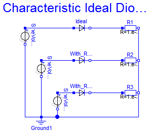
Three examples of ideal diodes are shown:
the totally ideal diode (Ideal) with all parameters to be zero,
the nearly ideal diode with Ron=0.1 and Goff=0.1
and the nearly ideal but displaced diode with Vknee=5 and Ron=0.1 and Goff=0.1.
The resistance and conductance are chosen untypically high since the slopes should be seen in the graphics.
Simulate until T=1 s. Plot in separate windows: Ideal.i versus Ideal.v, With_Ron_Goff.i versus With_Ron_Goff.v, With_Ron_Goff_Vknee.i versus With_Ron_Goff_Vknee.v
Extends from Modelica.Icons.Example (Icon for runnable examples).
model CharacteristicIdealDiodes "Characteristic of ideal diodes" extends Modelica.Icons.Example;Modelica.Electrical.Analog.Ideal.IdealDiode Ideal( Ron=0, Goff=0); Modelica.Electrical.Analog.Ideal.IdealDiode With_Ron_Goff( Ron=0.1, Goff=0.1); Modelica.Electrical.Analog.Ideal.IdealDiode With_Ron_Goff_Vknee( Ron=0.2, Goff=0.2, Vknee=5); Modelica.Electrical.Analog.Sources.SineVoltage SineVoltage1( V=10, offset=-9); Modelica.Electrical.Analog.Basic.Ground Ground1; Modelica.Electrical.Analog.Basic.Resistor R1(R=1.e-3); Modelica.Electrical.Analog.Basic.Resistor R2(R=1.e-3); Modelica.Electrical.Analog.Basic.Resistor R3(R=1.e-3); Modelica.Electrical.Analog.Sources.SineVoltage SineVoltage2( V=10, offset=0); Modelica.Electrical.Analog.Sources.SineVoltage SineVoltage3( V=10, offset=0); equationconnect(Ground1.p, SineVoltage1.n); connect(Ideal.n, R1.p); connect(With_Ron_Goff.n, R2.p); connect(With_Ron_Goff_Vknee.n, R3.p); connect(R1.n, R2.n); connect(R2.n, R3.n); connect(R3.n, Ground1.p); connect(SineVoltage2.p, Ideal.p); connect(SineVoltage2.n, Ground1.p); connect(SineVoltage1.p,With_Ron_Goff. p); connect(With_Ron_Goff_Vknee.p, SineVoltage3.p); connect(SineVoltage3.n, Ground1.p); end CharacteristicIdealDiodes;
Modelica.Electrical.Analog.Examples.CharacteristicThyristors
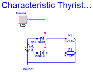
Two examples of thyristors are shown: the ideal thyristor and the ideal GTO thyristor with Vknee=5
Simulate until T=2 s. Plot in separate windows:
IdealThyristor1.i and IdealGTOThyristor1.i
IdealThyristor1.v and IdealGTOThyristor1.v
Extends from Modelica.Icons.Example (Icon for runnable examples).
model CharacteristicThyristors "Characteristic of ideal thyristors" extends Modelica.Icons.Example;Modelica.Electrical.Analog.Ideal.IdealThyristor IdealThyristor1( Vknee=5); Modelica.Electrical.Analog.Sources.SineVoltage SineVoltage1(V=10, offset=0); Modelica.Electrical.Analog.Basic.Ground Ground1; Modelica.Electrical.Analog.Basic.Resistor R3(R=1.e-3); Modelica.Blocks.Sources.BooleanStep BooleanStep1(startValue=false, startTime=1.25); Modelica.Electrical.Analog.Ideal.IdealGTOThyristor IdealGTOThyristor1( Vknee=0); Modelica.Electrical.Analog.Basic.Resistor R1(R=1.e-3); equationconnect(IdealThyristor1.n, R3.p); connect(Ground1.p, SineVoltage1.n); connect(SineVoltage1.p, IdealThyristor1.p); connect(BooleanStep1.y, IdealThyristor1.fire); connect(IdealGTOThyristor1.n, R1.p); connect(R3.n, R1.n); connect(R1.n, Ground1.p); connect(IdealGTOThyristor1.p, IdealThyristor1.p); connect(IdealGTOThyristor1.fire, IdealThyristor1.fire); end CharacteristicThyristors;
Modelica.Electrical.Analog.Examples.ChuaCircuit
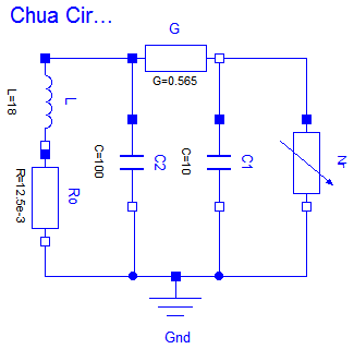
Chua';s circuit is the most simple nonlinear circuit which shows chaotic behaviour. The circuit consists of linear basic elements (capacitors, resistor, conductor, inductor), and one nonlinear element, which is called Chua';s diode. The chaotic behaviour is simulated.
The simulation end time should be set to 5e4. To get the chaotic behaviour please plot C1.v. Choose C2.v as the independent variable .
Reference:
Kennedy, M.P.: Three Steps to Chaos - Part I: Evolution. IEEE Transactions on CAS I 40 (1993)10, 640-656
Extends from Icons.Example (Icon for runnable examples).
encapsulated model ChuaCircuit "Chua's circuit, ns, V, A" import Modelica.Electrical.Analog.Basic; import Modelica.Electrical.Analog.Examples.Utilities; import Modelica.Icons; extends Icons.Example;Basic.Inductor L(L=18); Basic.Resistor Ro(R=12.5e-3); Basic.Conductor G(G=0.565); Basic.Capacitor C1(C=10, v(start=4)); Basic.Capacitor C2(C=100); Utilities.NonlinearResistor Nr( Ga(min=-1) = -0.757576, Gb(min=-1) = -0.409091, Ve=1); Basic.Ground Gnd; equationconnect(L.n, Ro.p); connect(C2.p, G.p); connect(L.p, G.p); connect(G.n, Nr.p); connect(C1.p, G.n); connect(Ro.n, Gnd.p); connect(C2.n, Gnd.p); connect(Gnd.p, C1.n); connect(Gnd.p, Nr.n); end ChuaCircuit;
Modelica.Electrical.Analog.Examples.DifferenceAmplifier
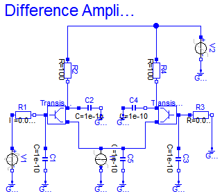
It is a simple NPN transistor amplifier circuit. The voltage difference between R1.p and R3.n is amplified. The output signal is the voltage between R2.n and R4.n. In this example the voltage at V1 is amplified because R3.n is grounded.
The simulation end time should be set to 1e- 8. Please plot the input voltage V1.v, and the output voltages R2.n.v, and R4.n.v.
Reference:
Tietze, U.; Schenk, Ch.: Halbleiter-Schaltungstechnik. Springer-Verlag Berlin Heidelberg NewYork 1980, p. 59
Extends from Icons.Example (Icon for runnable examples).
encapsulated model DifferenceAmplifier "Simple NPN transistor amplifier circuit" import Modelica.Electrical.Analog.Basic; import Modelica.Electrical.Analog.Sources; import Modelica.Electrical.Analog.Examples.Utilities; import Modelica.Icons; extends Icons.Example;Sources.ExpSineVoltage V1( V=0.2, freqHz=0.2e9, damping=0.1e8); Sources.RampVoltage V2(V=15, duration=1e-9); Sources.RampCurrent I1(I=0.16, duration=1e-9); Basic.Resistor R1(R=0.0001); Basic.Resistor R2(R=100); Basic.Resistor R3(R=0.0001); Basic.Resistor R4(R=100); Basic.Capacitor C1(C=1e-10); Basic.Capacitor C4(C=1e-10); Basic.Capacitor C5(C=1e-10); Basic.Capacitor C2(C=1e-10); Basic.Capacitor C3(C=1e-10); Basic.Ground Gnd1; Basic.Ground Gnd9; Basic.Ground Gnd3; Basic.Ground Gnd2; Basic.Ground Gnd6; Basic.Ground Gnd7; Basic.Ground Gnd8; Basic.Ground Gnd5; Basic.Ground Gnd4; Utilities.Transistor Transistor1; Utilities.Transistor Transistor2; equationconnect(V1.n, Gnd1.p); connect(C1.n, Gnd2.p); connect(I1.n, Gnd7.p); connect(C5.n, Gnd8.p); connect(C3.n, Gnd5.p); connect(R3.n, Gnd4.p); connect(C2.n, Gnd3.p); connect(C4.p, Gnd6.p); connect(I1.p, C5.p); connect(R1.p, V1.p); connect(R2.p, V2.p); connect(R4.p, V2.p); connect(V2.n, Gnd9.p); connect(R1.n, Transistor1.b); connect(Transistor1.b, C1.p); connect(Transistor1.c, C2.p); connect(R2.n, Transistor1.c); connect(Transistor1.e, I1.p); connect(Transistor2.b, R3.p); connect(Transistor2.b, C3.p); connect(C4.n, Transistor2.c); connect(R4.n, Transistor2.c); connect(C5.p, Transistor2.e); end DifferenceAmplifier;
Modelica.Electrical.Analog.Examples.HeatingMOSInverter
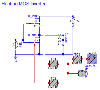
The heating MOS inverter shows a heat flow always if a transistor is leading.
Simulate until T=5 s. Plot in separate windows:
Sin.p.v and Capacitor1.p.v
HeatCapacitor1.port.T and H_PMOS.heatPort.T and H_NMOS.heatPort.T
H_PMOS.heatPort.Q_flow and H_NMOS.heatPort.Q_flow
Extends from Modelica.Icons.Example (Icon for runnable examples).
model HeatingMOSInverter "Heating MOS Inverter" extends Modelica.Icons.Example;Modelica.Electrical.Analog.Basic.Ground G; Modelica.Electrical.Analog.Sources.SineVoltage Sin(V=5, freqHz=1); Modelica.Electrical.Analog.Basic.Capacitor Capacitor1(C=0.00001); Modelica.Thermal.HeatTransfer.Components.HeatCapacitor HeatCapacitor1(C=0.01); Modelica.Thermal.HeatTransfer.Components.ThermalConductor TC1(G=0.01); Semiconductors.HeatingPMOS H_PMOS(useHeatPort=true); Semiconductors.HeatingNMOS H_NMOS(useHeatPort=true); Modelica.Electrical.Analog.Sources.RampVoltage V(V=5, duration=1.e-2); Modelica.Thermal.HeatTransfer.Components.ThermalConductor TC2(G=0.01); Modelica.Thermal.HeatTransfer.Sources.FixedTemperature FixedTemperature1(T= 300); Modelica.Thermal.HeatTransfer.Components.ThermalConductor TC3(G=0.01); equationconnect(Sin.n, G.p); connect(Capacitor1.n, G.p); connect(H_PMOS.S, H_NMOS.D); connect(H_NMOS.D, Capacitor1.p); connect(H_NMOS.B, H_NMOS.S); connect(H_NMOS.S, G.p); connect(H_PMOS.B, H_PMOS.D); connect(V.p, H_PMOS.D); connect(V.n, G.p); connect(TC1.port_b, HeatCapacitor1.port); connect(TC2.port_b, HeatCapacitor1.port); connect(TC1.port_a, H_PMOS.heatPort); connect(TC2.port_a, H_NMOS.heatPort); connect(TC3.port_b, FixedTemperature1.port); connect(TC3.port_a, HeatCapacitor1.port); connect(Sin.p, H_NMOS.G); connect(H_PMOS.G, Sin.p); end HeatingMOSInverter;
Modelica.Electrical.Analog.Examples.HeatingNPN_OrGate
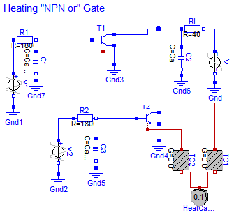
The heating "NPN or" gate shows a heat flow always if a transistor is leading.
Simulate until T=200 s. Plot in separate windows:
V1.v and V2.v and C2.v
HeatCapacitor1.port.T and T1.heatPort.T and T2.heatPort.T
T1.heatPort.Q_flow and T2.heatPort.Q_flow
Extends from Modelica.Icons.Example (Icon for runnable examples).
model HeatingNPN_OrGate "Heating NPN Or Gate" extends Modelica.Icons.Example; constant Modelica.SIunits.Capacitance CapVal=0; constant Modelica.SIunits.Time tauVal=0;Modelica.Thermal.HeatTransfer.Components.HeatCapacitor HeatCapacitor1(C=0.1); Modelica.Thermal.HeatTransfer.Components.ThermalConductor TC1(G=0.01); Modelica.Thermal.HeatTransfer.Components.ThermalConductor TC2(G=0.01); Modelica.Electrical.Analog.Sources.RampVoltage V(V=6, duration=5); Modelica.Electrical.Analog.Sources.TrapezoidVoltage V1( V=6, startTime=55, rising=5, width=15, falling=5, period=50, nperiod=10); Modelica.Electrical.Analog.Sources.TrapezoidVoltage V2( V=6, startTime=65, rising=5, width=15, falling=5, period=50, nperiod=10); Modelica.Electrical.Analog.Basic.Resistor R1(R=1800); Modelica.Electrical.Analog.Basic.Resistor R2(R=1800); Modelica.Electrical.Analog.Basic.Resistor RI(R=40); Modelica.Electrical.Analog.Basic.Ground Gnd; Modelica.Electrical.Analog.Basic.Ground Gnd1; Modelica.Electrical.Analog.Basic.Ground Gnd2; Modelica.Electrical.Analog.Basic.Ground Gnd3; Modelica.Electrical.Analog.Basic.Ground Gnd4; Modelica.Electrical.Analog.Basic.Capacitor C1(C=CapVal); Modelica.Electrical.Analog.Basic.Capacitor C2(C=CapVal); Modelica.Electrical.Analog.Basic.Capacitor C3(C=CapVal); Modelica.Electrical.Analog.Basic.Ground Gnd5; Modelica.Electrical.Analog.Basic.Ground Gnd6; Modelica.Electrical.Analog.Basic.Ground Gnd7; Semiconductors.HeatingNPN T1( Bf=100, Br=1, Is=1.e-14, Vak=0, Tauf=tauVal, Taur=tauVal, Ccs=CapVal, Cje=CapVal, Cjc=CapVal, Phie=1, Me=0.5, Phic=1, Mc=0.5, Gbc=1.e-12, Gbe=1.e-12, EMax=40, vt_t(start=0.01, fixed=false), useHeatPort=true); Semiconductors.HeatingNPN T2( Bf=100, Br=1, Is=1.e-14, Vak=0, Tauf=tauVal, Taur=tauVal, Ccs=CapVal, Cje=CapVal, Cjc=CapVal, Phie=1, Me=0.5, Phic=1, Mc=0.5, Gbc=1.e-12, Gbe=1.e-12, EMax=40, vt_t(start=0.01, fixed=false), useHeatPort=true); equationconnect(Gnd1.p, V1.n); connect(V1.p, R1.p); connect(RI.n, V.p); connect(Gnd.p, V.n); connect(V2.p, R2.p); connect(Gnd2.p, V2.n); connect(Gnd7.p, C1.n); connect(C2.p, RI.p); connect(Gnd6.p, C2.n); connect(C3.p, R2.n); connect(C1.p, R1.n); connect(Gnd5.p, C3.n); connect(T1.B, R1.n); connect(T1.E, Gnd3.p); connect(RI.p, T1.C); connect(T2.B, R2.n); connect(T2.E, Gnd4.p); connect(T2.C, RI.p); connect(TC1.port_b, HeatCapacitor1.port); connect(TC2.port_b, HeatCapacitor1.port); connect(TC2.port_a, T2.heatPort); connect(TC1.port_a, T1.heatPort); end HeatingNPN_OrGate;
Modelica.Electrical.Analog.Examples.HeatingResistor
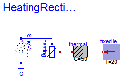
This is a very simple circuit consisting of a voltage source and a resistor. The loss power in the resistor is transported to the environment via its heatPort.
Extends from Modelica.Icons.Example (Icon for runnable examples).
model HeatingResistor "Heating resistor" extends Modelica.Icons.Example;Basic.HeatingResistor heatingResistor( R_ref=100, alpha=1e-3, T_ref=293.15); Modelica.Electrical.Analog.Basic.Ground G; Modelica.Electrical.Analog.Sources.SineVoltage SineVoltage1(V=220, freqHz=1); Modelica.Thermal.HeatTransfer.Components.ThermalConductor thermalConductor(G= 50); Thermal.HeatTransfer.Celsius.FixedTemperature fixedTemperature(T=20); equationconnect(SineVoltage1.n, G.p); connect(heatingResistor.heatPort, thermalConductor.port_a); connect(SineVoltage1.p, heatingResistor.p); connect(G.p, heatingResistor.n); connect(thermalConductor.port_b, fixedTemperature.port); end HeatingResistor;
Modelica.Electrical.Analog.Examples.HeatingRectifier
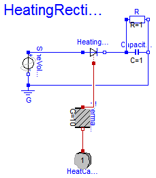
The heating rectifier shows a heat flow always if the electrical capacitor is loaded.
Simulate until T=5 s.Plot in separate windows:
SineVoltage1.v and Capacitor1.p.v
HeatCapacitor1.port.T and HeatingDiode1.heatPort.T
HeatingDiode1.heatPort.Q_flow
Extends from Modelica.Icons.Example (Icon for runnable examples).
model HeatingRectifier "Heating rectifier" extends Modelica.Icons.Example;Modelica.Electrical.Analog.Semiconductors.HeatingDiode HeatingDiode1( useHeatPort=true); Modelica.Electrical.Analog.Basic.Ground G; Modelica.Electrical.Analog.Sources.SineVoltage SineVoltage1(V=1, freqHz=1); Modelica.Electrical.Analog.Basic.Capacitor Capacitor1(C=1); Modelica.Thermal.HeatTransfer.Components.HeatCapacitor HeatCapacitor1(C=1); Modelica.Thermal.HeatTransfer.Components.ThermalConductor ThermalConductor1(G=10); Modelica.Electrical.Analog.Basic.Resistor R(R=1); equationconnect(SineVoltage1.p, HeatingDiode1.p); connect(SineVoltage1.n, G.p); connect(Capacitor1.n, G.p); connect(HeatingDiode1.n, Capacitor1.p); connect(HeatingDiode1.heatPort, ThermalConductor1.port_a); connect(ThermalConductor1.port_b, HeatCapacitor1.port); connect(R.p, Capacitor1.p); connect(R.n, Capacitor1.n); end HeatingRectifier;
Modelica.Electrical.Analog.Examples.NandGate
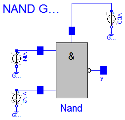
The nand gate is a basic CMOS building block. It consists of four CMOS transistors. The output voltage Nand.y.v is low if and only if the two input voltages at Nand.x1.v and Nand.x2.v are both high. In this way the nand functionality is realized.
The simulation end time should be set to 1e-7. Please plot the input voltages Nand.x1.v, d Nand.x2.v, and the output voltage Nand.y.v.
Reference:
Tietze, U.; Schenk, Ch.: Halbleiter-Schaltungstechnik. Springer-Verlag Berlin Heidelberg NewYork 1980, p. 157
Extends from Icons.Example (Icon for runnable examples).
encapsulated model NandGate "CMOS NAND Gate (see Tietze/Schenk, page 157)" import Modelica.Electrical.Analog.Basic; import Modelica.Electrical.Analog.Sources; import Modelica.Electrical.Analog.Examples.Utilities; import Modelica.Icons; extends Icons.Example;Sources.TrapezoidVoltage VIN1( V=3.5, startTime=20e-9, rising=1e-9, width=19e-9, falling=1.e-9, period=40e-9); Sources.TrapezoidVoltage VIN2( V=3.5, startTime=10e-9, rising=1e-9, width=19e-9, falling=1.e-9, period=40e-9); Sources.RampVoltage VDD(V=5, duration=1e-9); Basic.Ground Gnd1; Basic.Ground Gnd4; Basic.Ground Gnd5; Utilities.Nand Nand; equationconnect(VDD.n, Gnd1.p); connect(VIN1.n, Gnd4.p); connect(VIN2.n, Gnd5.p); connect(Nand.Vdd, VDD.p); connect(VIN1.p, Nand.x1); connect(VIN2.p, Nand.x2); end NandGate;
Modelica.Electrical.Analog.Examples.OvervoltageProtection
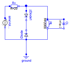
This example is a simple circuit for overvoltage protection. If the voltage zDiode_1.n.v is too high, the Diode zDiode_2 breaks through and the voltage gets down.
The simulation end time should be set to 0.4. To get the typical behaviour please plot sineVoltage.p.v, RL.p.v, zDiode_2.n.v and zDiode_1.n.i.
Extends from Modelica.Icons.Example (Icon for runnable examples).
model OvervoltageProtection "Example for Zener diodes" extends Modelica.Icons.Example;Modelica.Electrical.Analog.Sources.SineVoltage sineVoltage( offset=0, V=10, freqHz=5); Modelica.Electrical.Analog.Basic.Resistor Rv(R=20); Modelica.Electrical.Analog.Basic.Resistor RL(R=2000); Modelica.Electrical.Analog.Basic.Ground ground; Modelica.Electrical.Analog.Basic.Capacitor CL(C=1e-7); Semiconductors.ZDiode zDiode; Semiconductors.ZDiode zDiode1; equationconnect(sineVoltage.p, Rv.p); connect(RL.p, CL.p); connect(RL.n, CL.n); connect(sineVoltage.n, zDiode.p); connect(zDiode.p, ground.p); connect(zDiode.p, RL.n); connect(zDiode1.p, Rv.n); connect(RL.p, Rv.n); connect(zDiode1.n, zDiode.n); end OvervoltageProtection;
Modelica.Electrical.Analog.Examples.Rectifier
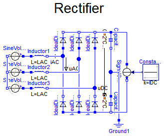
The rectifier example shows a B6 diode bridge fed by a three phase sinusoidal voltage, loaded by a DC current. DC capacitors start at ideal no-load voltage, thus making easier initial transient.
Simulate until T=0.1 s. Plot in separate windows:
uDC ... DC-voltage
iAC ... AC-currents 1..3
uAC ... AC-voltages 1..3 (distorted)
Try different load currents iDC = 0..approximately 500 A. You may watch losses (of the whole diode bridge) trying different diode parameters.
Extends from Modelica.Icons.Example (Icon for runnable examples).
| Type | Name | Default | Description |
|---|---|---|---|
| Voltage | VAC | 400 | RMS line-to-line [V] |
| Frequency | f | 50 | line frequency [Hz] |
| Inductance | LAC | 60E-6 | line inductor [H] |
| Resistance | Ron | 1E-3 | diode forward resistance [Ohm] |
| Conductance | Goff | 1E-3 | diode backward conductance [S] |
| Voltage | Vknee | 2 | diode threshold voltage [V] |
| Capacitance | CDC | 15E-3 | DC capacitance [F] |
| Current | IDC | 500 | load current [A] |
model Rectifier "B6 diode bridge" extends Modelica.Icons.Example; import Modelica.Electrical.Analog.Ideal; parameter Modelica.SIunits.Voltage VAC=400 "RMS line-to-line"; parameter Modelica.SIunits.Frequency f=50 "line frequency"; parameter Modelica.SIunits.Inductance LAC=60E-6 "line inductor"; parameter Modelica.SIunits.Resistance Ron=1E-3 "diode forward resistance"; parameter Modelica.SIunits.Conductance Goff=1E-3 "diode backward conductance"; parameter Modelica.SIunits.Voltage Vknee=2 "diode threshold voltage"; parameter Modelica.SIunits.Capacitance CDC=15E-3 "DC capacitance"; parameter Modelica.SIunits.Current IDC=500 "load current"; output Modelica.SIunits.Voltage uDC; output Modelica.SIunits.Current iAC[3]; output Modelica.SIunits.Voltage uAC[3]; output Modelica.SIunits.Power Losses;Modelica.Electrical.Analog.Sources.SineVoltage SineVoltage1(freqHz=f, V=VAC*sqrt(2/3)); Modelica.Electrical.Analog.Sources.SineVoltage SineVoltage2( freqHz=f, phase=-2/3*Modelica.Constants.pi, V=VAC*sqrt(2/3)); Modelica.Electrical.Analog.Sources.SineVoltage SineVoltage3( freqHz=f, phase=-4/3*Modelica.Constants.pi, V=VAC*sqrt(2/3)); Modelica.Electrical.Analog.Basic.Inductor Inductor1(L=LAC); Modelica.Electrical.Analog.Basic.Inductor Inductor2(L=LAC); Modelica.Electrical.Analog.Basic.Inductor Inductor3(L=LAC); Ideal.IdealDiode IdealDiode1( Ron=Ron, Goff=Goff, Vknee=Vknee); Ideal.IdealDiode IdealDiode2( Ron=Ron, Goff=Goff, Vknee=Vknee); Ideal.IdealDiode IdealDiode3( Ron=Ron, Goff=Goff, Vknee=Vknee); Ideal.IdealDiode IdealDiode4( Ron=Ron, Goff=Goff, Vknee=Vknee); Ideal.IdealDiode IdealDiode5( Ron=Ron, Goff=Goff, Vknee=Vknee); Ideal.IdealDiode IdealDiode6( Ron=Ron, Goff=Goff, Vknee=Vknee); Modelica.Electrical.Analog.Basic.Capacitor Capacitor1(C=2*CDC); Modelica.Electrical.Analog.Basic.Capacitor Capacitor2(C=2*CDC); Modelica.Electrical.Analog.Basic.Ground Ground1; Modelica.Electrical.Analog.Sources.SignalCurrent SignalCurrent1; Modelica.Blocks.Sources.Constant Constant1(k=IDC); initial equation Capacitor1.v = VAC*sqrt(2)/2; Capacitor2.v = VAC*sqrt(2)/2; equation uDC = Capacitor1.v + Capacitor2.v; iAC = {Inductor1.i,Inductor2.i,Inductor3.i}; uAC[1] = Inductor1.n.v - Inductor2.n.v; uAC[2] = Inductor2.n.v - Inductor3.n.v; uAC[3] = Inductor3.n.v - Inductor1.n.v; Losses = IdealDiode1.v*IdealDiode1.i + IdealDiode2.v*IdealDiode2.i + IdealDiode3.v*IdealDiode3.i + IdealDiode4.v*IdealDiode4.i + IdealDiode5.v*IdealDiode5.i + IdealDiode6.v*IdealDiode6.i;connect(SineVoltage1.n, SineVoltage2.n); connect(SineVoltage2.n, SineVoltage3.n); connect(SineVoltage1.p, Inductor1.p); connect(SineVoltage2.p, Inductor2.p); connect(SineVoltage3.p, Inductor3.p); connect(IdealDiode1.p, IdealDiode4.n); connect(IdealDiode2.p, IdealDiode5.n); connect(IdealDiode3.p, IdealDiode6.n); connect(IdealDiode1.n, IdealDiode2.n); connect(IdealDiode2.n, IdealDiode3.n); connect(IdealDiode4.p, IdealDiode5.p); connect(IdealDiode5.p, IdealDiode6.p); connect(Capacitor2.n, IdealDiode6.p); connect(IdealDiode3.n, Capacitor1.p); connect(Capacitor1.n, Capacitor2.p); connect(Capacitor2.p, Ground1.p); connect(Capacitor1.p, SignalCurrent1.p); connect(SignalCurrent1.n, Capacitor2.n); connect(Constant1.y, SignalCurrent1.i); connect(Inductor1.n, IdealDiode1.p); connect(Inductor2.n, IdealDiode2.p); connect(Inductor3.n, IdealDiode3.p); end Rectifier;
Modelica.Electrical.Analog.Examples.ShowSaturatingInductor
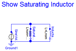
This simple circuit uses the saturating inductor which has a changing inductivity.
This circuit should be simulated until 1 s. Compare SaturatingInductance1.p.i with Inductance1.p.i to see the difference between saturating and ideal inductor.
Extends from Modelica.Icons.Example (Icon for runnable examples).
| Type | Name | Default | Description |
|---|---|---|---|
| Inductance | Lzer | 2 | Inductance near current=0 [H] |
| Inductance | Lnom | 1 | Nominal inductance at Nominal current [H] |
| Current | Inom | 1 | Nominal current [A] |
| Inductance | Linf | 0.5 | Inductance at large currents [H] |
| Voltage | U | 1.25 | Source voltage (peak) [V] |
| Frequency | f | 1/(2*Modelica.Constants.pi) | Source frequency [Hz] |
| Angle | phase | Modelica.Constants.pi/2 | Source voltage phase shift [rad] |
model ShowSaturatingInductor
  "Simple demo to show behaviour of SaturatingInductor component"
  extends Modelica.Icons.Example;
  parameter Modelica.SIunits.Inductance Lzer=2 "Inductance near current=0";
  parameter Modelica.SIunits.Inductance Lnom=1
    "Nominal inductance at Nominal current";
  parameter Modelica.SIunits.Current Inom=1 "Nominal current";
  parameter Modelica.SIunits.Inductance Linf=0.5 "Inductance at large currents";
  parameter Modelica.SIunits.Voltage U=1.25 "Source voltage (peak)";
  parameter Modelica.SIunits.Frequency f=1/(2*Modelica.Constants.pi)
    "Source frequency";
  parameter Modelica.SIunits.Angle phase=Modelica.Constants.pi/2
    "Source voltage phase shift";
  //output Modelica.SIunits.Voltage v "Voltage drop over saturating inductor";
  //output Modelica.SIunits.Current i "Current across saturating inductor";
  Modelica.Electrical.Analog.Sources.SineVoltage SineVoltage1(
    V=U,
    phase=phase,
    freqHz=f);
  Modelica.Electrical.Analog.Basic.Ground Ground1;
  Modelica.Electrical.Analog.Basic.SaturatingInductor SaturatingInductance1(
    Lzer=Lzer,
    Lnom=Lnom,
    Inom=Inom,
    Linf=Linf);
  Basic.Inductor Inductance1(L=Lnom);
equation
  //v=SaturatingInductance1.v;
  //i=SaturatingInductance1.i;
  connect(SineVoltage1.n, Ground1.p);
  connect(SineVoltage1.n, SaturatingInductance1.n);
  connect(SaturatingInductance1.p, SineVoltage1.p);
  connect(Inductance1.p, SineVoltage1.p);
  connect(Inductance1.n, SineVoltage1.n);
end ShowSaturatingInductor;
Modelica.Electrical.Analog.Examples.ShowVariableResistor
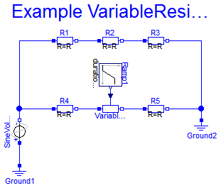
It is a simple test circuit for the VariableResistor. The VariableResistor sould be compared with R2.
Simulate until T=1 s.
Extends from Modelica.Icons.Example (Icon for runnable examples).
model ShowVariableResistor "Simple demo of a VariableResistor model" extends Modelica.Icons.Example;Modelica.Electrical.Analog.Basic.VariableResistor VariableResistor; Modelica.Electrical.Analog.Basic.Ground Ground1; Modelica.Electrical.Analog.Basic.Ground Ground2; Modelica.Electrical.Analog.Basic.Resistor R1; Modelica.Electrical.Analog.Basic.Resistor R2; Modelica.Electrical.Analog.Basic.Resistor R3; Modelica.Electrical.Analog.Basic.Resistor R4; Modelica.Electrical.Analog.Basic.Resistor R5; Modelica.Electrical.Analog.Sources.SineVoltage SineVoltage1; Modelica.Blocks.Sources.Ramp Ramp1(height=5, offset=2); equationconnect(R1.n, R2.p); connect(R2.n, R3.p); connect(R4.n, VariableResistor.p); connect(VariableResistor.n, R5.p); connect(R3.n, Ground2.p); connect(Ground2.p, R5.n); connect(SineVoltage1.p, Ground1.p); connect(SineVoltage1.n, R1.p); connect(SineVoltage1.n, R4.p); connect(Ramp1.y, VariableResistor.R); end ShowVariableResistor;
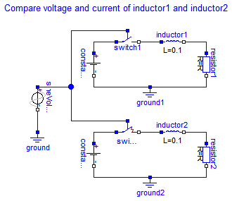
Modelica.Electrical.Analog.Examples.SwitchWithArc
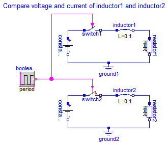
This example is to compare the behaviour of switch models with and without an electric arc taking into consideration.
switch1.i and switch2.i The difference in the closing area shows that the simple arc model avoids the suddenly switching.
Extends from Modelica.Icons.Example (Icon for runnable examples).
model SwitchWithArc "Comparison of switch models both with and without arc" extends Modelica.Icons.Example;Modelica.Blocks.Sources.BooleanPulse booleanPulse; Modelica.Electrical.Analog.Basic.Ground ground1; Modelica.Electrical.Analog.Sources.ConstantVoltage constantVoltage1(V=50); Modelica.Electrical.Analog.Basic.Inductor inductor1(L=0.1); Modelica.Electrical.Analog.Basic.Resistor resistor1; Modelica.Electrical.Analog.Ideal.IdealClosingSwitch switch1; Modelica.Electrical.Analog.Basic.Ground ground2; Modelica.Electrical.Analog.Sources.ConstantVoltage constantVoltage2(V=50); Modelica.Electrical.Analog.Basic.Inductor inductor2(L=0.1); Modelica.Electrical.Analog.Basic.Resistor resistor2; Modelica.Electrical.Analog.Ideal.CloserWithArc switch2; equationconnect(inductor1.n,resistor1. p); connect(resistor1.n,ground1. p); connect(constantVoltage1.n,ground1. p); connect(switch1.n,inductor1. p); connect(constantVoltage1.p,switch1. p); connect(inductor2.n,resistor2. p); connect(resistor2.n,ground2. p); connect(constantVoltage2.n,ground2. p); connect(switch2.n,inductor2. p); connect(constantVoltage2.p,switch2. p); connect(booleanPulse.y, switch1.control); connect(booleanPulse.y, switch2.control); end SwitchWithArc;
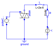
Modelica.Electrical.Analog.Examples.ThyristorBehaviourTest
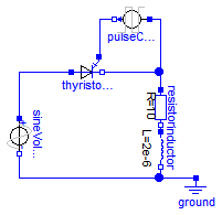
This is a simple testcircuit, to test the behavior of the thysistor model.
Interesting values to plot are Cathode.v, Gate.v and sineVoltage.p.v. and in another plot window pulseCurrent.p.i
The simulation time should be trom 0 seconds to 2e-4 seconds.
Extends from Modelica.Icons.Example (Icon for runnable examples).
model ThyristorBehaviourTest "Thyristor demonstration example" extends Modelica.Icons.Example;Modelica.Electrical.Analog.Basic.Ground ground; Modelica.Electrical.Analog.Sources.SineVoltage sineVoltage( V=30, freqHz= 10000); Modelica.Electrical.Analog.Basic.Resistor resistor(R=10); Modelica.Electrical.Analog.Sources.PulseCurrent pulseCurrent( width=10, period=0.0001, startTime=0.00002, I=0.005); Modelica.Electrical.Analog.Semiconductors.Thyristor thyristor_v4_1; Modelica.Electrical.Analog.Basic.Inductor inductor(L=2e-6); equationconnect(sineVoltage.n, ground.p); connect(sineVoltage.p, thyristor_v4_1.Anode); connect(resistor.p, thyristor_v4_1.Cathode); connect(pulseCurrent.n, thyristor_v4_1.Gate); connect(resistor.p, pulseCurrent.p); connect(resistor.n, inductor.p); connect(inductor.n, ground.p); end ThyristorBehaviourTest;
Modelica.Electrical.Analog.Examples.AmplifierWithOpAmpDetailed
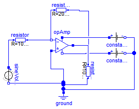
With the test circuit AmplifierWithOpAmpDetailed a time domain analysis of the example arrangement with a sinusoidal input voltage (12 V amplitude, frequency 1 kHz) using the operational amplifier model OpAmpDetailed is carried out. The working voltages are 15 V and -15 V.
Extends from Modelica.Icons.Example (Icon for runnable examples).
model AmplifierWithOpAmpDetailed "Simple Amplifier circuit which uses OpAmpDetailed" extends Modelica.Icons.Example;Modelica.Electrical.Analog.Basic.OpAmpDetailed opAmp; Modelica.Electrical.Analog.Basic.Resistor resistor(R=10000); Modelica.Electrical.Analog.Basic.Resistor resistor1(R=20000); Modelica.Electrical.Analog.Basic.Resistor resistor2(R=10000); Modelica.Electrical.Analog.Sources.SineVoltage sineVoltage(V=12, freqHz=1000); Modelica.Electrical.Analog.Basic.Ground ground; Modelica.Electrical.Analog.Sources.ConstantVoltage constantVoltage(V=15); Modelica.Electrical.Analog.Sources.ConstantVoltage constantVoltage1(V=-15); equationconnect(resistor.n, opAmp.m); connect(resistor1.n, resistor2.p); connect(resistor.p, sineVoltage.p); connect(resistor1.p, opAmp.m); connect(sineVoltage.n, ground.p); connect(opAmp.p, ground.p); connect(resistor2.n, ground.p); connect(opAmp.p_supply, constantVoltage.p); connect(opAmp.m_supply, constantVoltage1.p); connect(constantVoltage.n, constantVoltage1.n); connect(constantVoltage1.n, ground.p); connect(opAmp.outp, resistor2.p); end AmplifierWithOpAmpDetailed;
Modelica.Electrical.Analog.Examples.CompareTransformers
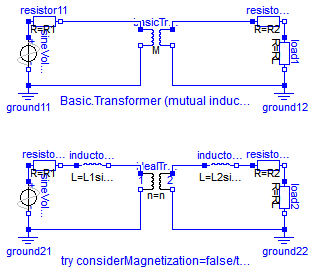
This example is to demonstrate the behaviour of transformer models. The Basic.Transformer, which consists of mutual coupled inductors, is compared with the ideal transformer model. If the ideal model is used with considerMagnetization=true leakage inductances are taken into account, otherwise not. The example is constructed in such a way that the ideal transformer circuit with considerMagnetization=true shows the same behaviour as the basic transformer.
Simulate until T=50 s with both considerMagnetization=false and considerMagnetization=true of the ideal transformer.
Plot in separate windows for comparison:
basicTransformer.p1.v and idealTransformer.p1.v
basicTransformer.p1.i and idealTransformer.p1.i
basicTransformer.p2.v and idealTransformer.p2.v
basicTransformer.p2.i and idealTransformer.p2.i
Extends from Modelica.Icons.Example (Icon for runnable examples).
| Type | Name | Default | Description |
|---|---|---|---|
| Voltage | Vdc | 0.1 | DC offset of voltage source [V] |
| Voltage | Vpeak | 0.1 | Peak voltage of voltage source [V] |
| Frequency | f | 10 | Frequency of voltage source [Hz] |
| Angle | phi0 | pi/2 | Phase of voltage source [rad] |
| Real | n | 2 | Turns ratio primary:secondary voltage |
| Resistance | R1 | 0.01 | Primary resistance w.r.t. primary side [Ohm] |
| Inductance | L1sigma | 0.05/(2*pi*f) | Primary leakage inductance w.r.t. primary side [H] |
| Inductance | Lm1 | 10./(2*pi*f) | Magnetizing inductance w.r.t. primary side [H] |
| Inductance | L2sigma | 0.05/(2*pi*f)/n^2 | Secondary leakage inductance w.r.t. secondary side [H] |
| Resistance | R2 | 0.01/n^2 | Secondary resistance w.r.t. secondary side [Ohm] |
| Resistance | RL | 1/n^2 | Load resistance [Ohm] |
model CompareTransformers
  "Transformer circuit to show the magnetization facilities"

  extends Modelica.Icons.Example;
  constant Modelica.SIunits.Angle pi = Modelica.Constants.pi;
  parameter Modelica.SIunits.Voltage Vdc=0.1 "DC offset of voltage source";
  parameter Modelica.SIunits.Voltage Vpeak=0.1 "Peak voltage of voltage source";
  parameter Modelica.SIunits.Frequency f=10 "Frequency of voltage source";
  parameter Modelica.SIunits.Angle phi0=pi/2 "Phase of voltage source";
  parameter Real n=2 "Turns ratio primary:secondary voltage";
  parameter Modelica.SIunits.Resistance R1=0.01
    "Primary resistance w.r.t. primary side";
  parameter Modelica.SIunits.Inductance L1sigma=0.05/(2*pi*f)
    "Primary leakage inductance w.r.t. primary side";
  parameter Modelica.SIunits.Inductance Lm1= 10./(2*pi*f)
    "Magnetizing inductance w.r.t. primary side";
  parameter Modelica.SIunits.Inductance L2sigma=0.05/(2*pi*f)/n^2
    "Secondary leakage inductance w.r.t. secondary side";
  parameter Modelica.SIunits.Resistance R2=0.01/n^2
    "Secondary resistance w.r.t. secondary side";
  parameter Modelica.SIunits.Resistance RL=1/n^2 "Load resistance";
  final parameter Modelica.SIunits.Inductance L1=L1sigma + M*n
    "Primary no-load inductance";
  final parameter Modelica.SIunits.Inductance L2=L2sigma + M/n
    "Secondary no-load inductance";
  final parameter Modelica.SIunits.Inductance M=Lm1/n "Mutual inductance";
  output Modelica.SIunits.Voltage v1B = resistor11.n.v
    "Primary voltage, basic transformer";
  output Modelica.SIunits.Current i1B = resistor11.i
    "Primary current, basic transformer";
  output Modelica.SIunits.Voltage v2B = resistor12.p.v
    "Secondary voltage, basic transformer";
  output Modelica.SIunits.Current i2B = resistor12.i
    "Secondary current, basic transformer";
  output Modelica.SIunits.Voltage v1I = resistor21.n.v
    "Primary voltage, basic transformer";
  output Modelica.SIunits.Current i1I = resistor21.i
    "Primary current, basic transformer";
  output Modelica.SIunits.Voltage v2I = resistor22.p.v
    "Secondary voltage, basic transformer";
  output Modelica.SIunits.Current i2I = resistor22.i
    "Secondary current, basic transformer";
  Modelica.Electrical.Analog.Sources.SineVoltage sineVoltage1(
    V=Vpeak,
    phase=phi0,
    freqHz=f,
    offset=Vdc);
  Modelica.Electrical.Analog.Basic.Ground ground11;
  Modelica.Electrical.Analog.Basic.Resistor resistor11(R=R1);
  Modelica.Electrical.Analog.Basic.Resistor resistor12(R=R2);
  Modelica.Electrical.Analog.Basic.Resistor load1(R=RL);
  Modelica.Electrical.Analog.Basic.Ground ground12;
  Modelica.Electrical.Analog.Sources.SineVoltage sineVoltage2(
    V=Vpeak,
    phase=phi0,
    freqHz=f,
    offset=Vdc);
  Modelica.Electrical.Analog.Basic.Ground ground21;
  Modelica.Electrical.Analog.Basic.Resistor resistor21(R=R1);
  Modelica.Electrical.Analog.Basic.Inductor inductor21(L=L1sigma);
  Modelica.Electrical.Analog.Basic.Inductor inductor22(L=L2sigma);
  Modelica.Electrical.Analog.Basic.Resistor resistor22(R=R2);
  Modelica.Electrical.Analog.Basic.Resistor load2(R=RL);
  Modelica.Electrical.Analog.Basic.Ground ground22;
  Modelica.Electrical.Analog.Basic.Transformer basicTransformer(
    L1=L1,
    L2=L2,
    M=M);
  Modelica.Electrical.Analog.Ideal.IdealTransformer idealTransformer(n=n,
      Lm1=Lm1,
    considerMagnetization=false);
equation
  connect(sineVoltage1.n, ground11.p);
  connect(sineVoltage1.p, resistor11.p);
  connect(load1.n, ground12.p);
  connect(resistor12.n, load1.p);
  connect(sineVoltage2.n, ground21.p);
  connect(sineVoltage2.p, resistor21.p);
  connect(resistor21.n, inductor21.p);
  connect(inductor22.n, resistor22.p);
  connect(load2.n, ground22.p);
  connect(resistor22.n, load2.p);
  connect(ground11.p, basicTransformer.n1);
  connect(basicTransformer.n2, ground12.p);
  connect(basicTransformer.p1, resistor11.n);
  connect(basicTransformer.p2, resistor12.p);
  connect(ground21.p, idealTransformer.n1);
  connect(ground22.p, idealTransformer.n2);
  connect(idealTransformer.p1, inductor21.n);
  connect(idealTransformer.p2, inductor22.p);
end CompareTransformers;
Modelica.Electrical.Analog.Examples.ControlledSwitchWithArc
This example is to compare the behaviour of switch models with and without an electric arc taking into consideration.
switch1.i and switch2.i The difference in the closing area shows that the simple arc model avoids the suddenly switching.
Extends from Modelica.Icons.Example (Icon for runnable examples).
model ControlledSwitchWithArc "Comparison of controlled switch models both with and without arc" extends Modelica.Icons.Example;Modelica.Electrical.Analog.Basic.Ground ground1; Modelica.Electrical.Analog.Sources.ConstantVoltage constantVoltage1(V=50); Modelica.Electrical.Analog.Basic.Inductor inductor1(L=0.1); Modelica.Electrical.Analog.Basic.Resistor resistor1; Modelica.Electrical.Analog.Ideal.ControlledIdealClosingSwitch switch1; Modelica.Electrical.Analog.Basic.Ground ground2; Modelica.Electrical.Analog.Sources.ConstantVoltage constantVoltage2(V=50); Modelica.Electrical.Analog.Basic.Inductor inductor2(L=0.1); Modelica.Electrical.Analog.Basic.Resistor resistor2; Modelica.Electrical.Analog.Ideal.ControlledCloserWithArc switch2; Modelica.Electrical.Analog.Sources.SineVoltage sineVoltage(V=1, freqHz=1); Modelica.Electrical.Analog.Basic.Ground ground; equationconnect(inductor1.n,resistor1. p); connect(resistor1.n,ground1. p); connect(constantVoltage1.n,ground1. p); connect(switch1.n,inductor1. p); connect(constantVoltage1.p,switch1. p); connect(inductor2.n,resistor2. p); connect(resistor2.n,ground2. p); connect(constantVoltage2.n,ground2. p); connect(switch2.n,inductor2. p); connect(constantVoltage2.p,switch2. p); connect(sineVoltage.p, switch1.control); connect(sineVoltage.p, switch2.control); connect(sineVoltage.n, ground.p); end ControlledSwitchWithArc;
Modelica.Electrical.Analog.Examples.SimpleTriacCircuit
The simple TRIAC example shows how the SimpleTriac is used within an alternating current circuit.
The TRIAC is not conductiong until the Gate input g becomes positive. Then it becomes "conducting". If the TRIAC voltage changes its direction, the TRIAC becomes blocking. Due to the antiparallel connection of the internal two thyristors the same behavior is repeated in the negative half-wave.
Simulate until 0.001 seconds. Display V.p.v (input voltage), simpleTriac.g.i (gate input), and both simplelTriac.n.v and simpleTriac.n.i, which demonstrate the TRIAC behavior.
Extends from Modelica.Icons.Example (Icon for runnable examples).
model SimpleTriacCircuit "Simple triac test circuit" extends Modelica.Icons.Example;Modelica.Electrical.Analog.Basic.Ground ground; Modelica.Electrical.Analog.Basic.Inductor L(L=2e-6); Modelica.Electrical.Analog.Basic.Resistor R(R=10); Modelica.Electrical.Analog.Sources.SineVoltage V(V=30, freqHz=10000); Modelica.Electrical.Analog.Semiconductors.SimpleTriac simpleTriac(VDRM=400, VRRM=400); Modelica.Electrical.Analog.Sources.PulseCurrent pulseCurrent( I=0.005, width=10, startTime=0.00002, period=0.00005); equationconnect(L.n, R.p); connect(R.n, V.p); connect(V.n, ground.p); connect(simpleTriac.p, ground.p); connect(simpleTriac.n, L.p); connect(pulseCurrent.n, simpleTriac.g); connect(pulseCurrent.p, ground.p); end SimpleTriacCircuit;
Modelica.Electrical.Analog.Examples.IdealTriacCircuit
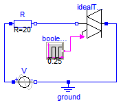
The simple ideal TRIAC example shows how a triac is used within an alternating current circuit.
The TRIAC is not conductiong until the Boolean input becomes true (internally coded by 1, therefore the input is called fire1). Then it becomes "conducting", the knee voltage is reached. If the TRIAC voltage falls below the knee voltage, the TRIAC becomes blocking. Due to the antiparallel connection of the internal two thyristors the same behavior is repeated in the negative half-wave.
Simulate until 2 seconds. Display V.p.v (input voltage), booleanPulse.y (fire1 input), and both idealTriac.n.v and idealTriac.n.i, which demonstrate the TRIAC behavior.
Extends from Modelica.Icons.Example (Icon for runnable examples).
model IdealTriacCircuit "Ideal triac test circuit" extends Modelica.Icons.Example;Modelica.Electrical.Analog.Basic.Ground ground; Modelica.Electrical.Analog.Basic.Resistor R(R=20); Modelica.Electrical.Analog.Sources.SineVoltage V(V=5, freqHz=2); Modelica.Blocks.Sources.BooleanPulse booleanPulse(width=50, period=0.25, startTime=0.1); Modelica.Electrical.Analog.Ideal.IdealTriac idealTriac; equationconnect(V.n, ground.p); connect(R.p, V.p); connect(R.n, idealTriac.n); connect(idealTriac.p, ground.p); connect(idealTriac.fire1, booleanPulse.y); end IdealTriacCircuit;
Modelica.Electrical.Analog.Examples.AD_DA_conversion
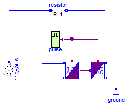
The simple converter circuit converts an analog sine signal into a N-bit (by default a 4 bit) logic signal, which is converted backward into an analog signal.
Compare the input voltage (aD_Converter.p.v) with the output voltage (dA_Converter.p.v). By changeing N the influence of the digital signal width can be studied. Otherwise the trigger frequency pulse.period can be changed to see its influence.
Extends from Modelica.Icons.Example (Icon for runnable examples).
| Type | Name | Default | Description |
|---|---|---|---|
| Integer | N | 7 | Digital signal width |
model AD_DA_conversion "Conversion circuit" extends Modelica.Icons.Example; parameter Integer N=7 "Digital signal width";Modelica.Electrical.Analog.Ideal.AD_Converter aD_Converter(N=N); Modelica.Electrical.Digital.Sources.Pulse pulse( pulse=Modelica.Electrical.Digital.Interfaces.Logic.'1', quiet=Modelica.Electrical.Digital.Interfaces.Logic.'0', nperiod=-1, width=1, period=0.001, startTime=0); Modelica.Electrical.Analog.Ideal.DA_Converter dA_Converter(N=N); Modelica.Electrical.Analog.Basic.Ground ground; Modelica.Electrical.Analog.Sources.SineVoltage sineVoltage( V=5, freqHz=10, offset=5); Modelica.Electrical.Analog.Basic.Resistor resistor(R=1); equationconnect(pulse.y, aD_Converter.trig); connect(sineVoltage.p, aD_Converter.p); connect(sineVoltage.n, aD_Converter.n); connect(ground.p, sineVoltage.n); connect(sineVoltage.p, resistor.p); connect(dA_Converter.trig, pulse.y); connect(aD_Converter.y, dA_Converter.x); connect(dA_Converter.p, resistor.n); connect(dA_Converter.n, ground.p); end AD_DA_conversion;
 Modelica.Electrical.Analog.Examples.CauerLowPassSC.Rn
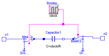
This model is a negative resistor without thermal behavior which is described as a switched capacitor model (care for the schematic).
The clock source is inside the model, its frequency can be chosen by parameter. Also the resistance is a parameter, it has to be positive. The internal (switched) capacitor is parametrized in such a way that the total resistance is independently from the frequency equal to the negative value of the negative resistance parameter.
| Type | Name | Default | Description |
|---|---|---|---|
| Time | clock | 1 | Clock [s] |
| Resistance | R | 1 | Resistance [Ohm] |
| Type | Name | Description |
|---|---|---|
| NegativePin | n1 | |
| NegativePin | n2 |
model Rn "Negative resistance"
  parameter Modelica.SIunits.Time clock=1 "Clock";
  parameter Modelica.SIunits.Resistance R(min=Modelica.Constants.eps)=1
    "Resistance";
  Modelica.Blocks.Sources.BooleanPulse BooleanPulse1(period=clock);

  Modelica.Electrical.Analog.Basic.Capacitor Capacitor1(C=clock/R);
  Modelica.Electrical.Analog.Ideal.IdealCommutingSwitch IdealCommutingSwitch1;
  Modelica.Electrical.Analog.Ideal.IdealCommutingSwitch IdealCommutingSwitch2;
  Modelica.Electrical.Analog.Basic.Ground Ground1;
  Modelica.Electrical.Analog.Basic.Ground Ground2;
  Modelica.Electrical.Analog.Interfaces.NegativePin n1;
  Modelica.Electrical.Analog.Interfaces.NegativePin n2;
equation
  connect(IdealCommutingSwitch1.p,Capacitor1. p);
  connect(Capacitor1.n,IdealCommutingSwitch2. p);
  connect(IdealCommutingSwitch2.control,BooleanPulse1. y);
  connect(IdealCommutingSwitch1.control,BooleanPulse1. y);
  connect(Ground2.p,IdealCommutingSwitch2. n2);
  connect(IdealCommutingSwitch2.n1,n2);
  connect(n1, IdealCommutingSwitch1.n2);
  connect(Ground1.p, IdealCommutingSwitch1.n1);
end Rn;
 Modelica.Electrical.Analog.Examples.CauerLowPassSC.Rp
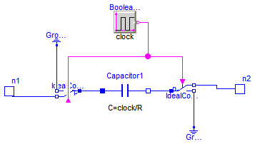
This model is a positive resistor without thermal behavior which is described as a switched capacitor model (care for the schematic).
The clock source is inside the model, its frequency can be chosen by parameter. Also the resistance is a parameter, it has to be positive. The internal (switched) capacitor is parametrized in such a way that the total resistance is independently from the frequency equal to the resistance parameter.
| Type | Name | Default | Description |
|---|---|---|---|
| Time | clock | 1 | Clock [s] |
| Resistance | R | 1 | Resistance [Ohm] |
| Type | Name | Description |
|---|---|---|
| NegativePin | n1 | |
| NegativePin | n2 |
model Rp "Positive resistance"

  parameter Modelica.SIunits.Time clock=1 "Clock";
  parameter Modelica.SIunits.Resistance R(min=Modelica.Constants.eps)=1
    "Resistance";
  Modelica.Blocks.Sources.BooleanPulse BooleanPulse1(period=clock);
  Modelica.Electrical.Analog.Basic.Capacitor Capacitor1(C=clock/R);
  Modelica.Electrical.Analog.Ideal.IdealCommutingSwitch IdealCommutingSwitch1;
  Modelica.Electrical.Analog.Ideal.IdealCommutingSwitch IdealCommutingSwitch2;
  Modelica.Electrical.Analog.Basic.Ground Ground1;
  Modelica.Electrical.Analog.Basic.Ground Ground2;
  Modelica.Electrical.Analog.Interfaces.NegativePin n1;
  Modelica.Electrical.Analog.Interfaces.NegativePin n2;
equation
  connect(IdealCommutingSwitch1.p, Capacitor1.p);
  connect(Capacitor1.n, IdealCommutingSwitch2.p);
  connect(IdealCommutingSwitch2.control, BooleanPulse1.y);
  connect(IdealCommutingSwitch1.control, BooleanPulse1.y);
  connect(Ground1.p, IdealCommutingSwitch1.n2);
  connect(Ground2.p, IdealCommutingSwitch2.n2);
  connect(IdealCommutingSwitch1.n1, n1);
  connect(IdealCommutingSwitch2.n1, n2);
end Rp;