Buildings.Fluid.HeatExchangers.ActiveBeams.UsersGuide
User's Guide
Information
This package contains models of active beams. Active beams are devices used for heating, cooling and ventilation of spaces. A schematic diagram of an active beam unit is given below.
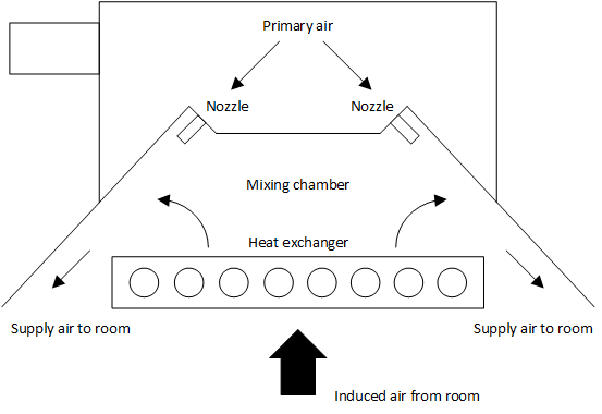
The active beam unit consists of a primary air plenum, a mixing chamber, a heat exchanger (coil) and several nozzles. Typically, an air-handling unit supplies primary air to the active beams. The primary air is discharged to the mixing chamber through the nozzles. This generates a low-pressure region which induces air from the room up through the heat exchanger, where hot or cold water is circulating. The conditioned induced air is then mixed with primary air, and the mixture descents back to the space.
This package contains two models. The model Buildings.Fluid.HeatExchangers.ActiveBeams.Cooling is for cooling only, while the model Buildings.Fluid.HeatExchangers.ActiveBeams.CoolingAndHeating has two water streams, one for heating and one for cooling.
Model equations for cooling
The performance of the model Buildings.Fluid.HeatExchangers.ActiveBeams.Cooling is computed based on manufacturer data specified in the package Buildings.Fluid.HeatExchangers.ActiveBeams.Data.
For off-design conditions, the performance is adjusted using modification factors that account for changes in water flow rate, primary air flow rate and temperature difference. The total heat flow rate of the active beam unit is the sum of the heat flow rate provided by the primary air supply Qsa and the cooling heat flow rate provided by the beam convector Qc,Beam which injects room air and mixes it with the primary air.
The heat flow rate Qsa is delivered to a thermal zone through the fluid ports, while the heat flow rate from the convector Qc,Beam is coupled directly to the heat port. See for example Buildings.Fluid.HeatExchangers.ActiveBeams.Examples.CoolingOnly for how to connect these heat flow rates to a control volume.
The primary air contribution is
Qsa = ṁsa cp,sa (Tsa-Tz)
where ṁsa is the primary air mass flow rate, cp,sa is the air specific heat capacity, Tsa is the primary air temperature and Tz is the zone air temperature.
The heat flow rate of the beam convector Qc,Beam is determined using the rated capacity which is modified by three separate functions as
Qc,Beam = Qc,nominal fΔT ( ΔTc ⁄ ΔTc,nominal ) fsa( ṁsa ⁄ ṁsa,nominal ) fw( ṁc,w ),
the modification factors are as follows: The modification factor fΔT(·) describes how the capacity is adjusted to account for the temperature difference between the zone air and the water entering the convector. The independent variable is the ratio between the current temperature difference ΔTc and the temperature difference used to rate beam performance ΔTc,nominal. The temperature difference is
ΔTc = Tcw-Tz,
where Tcw is the chilled water temperature entering the convector. The modification factor fsa(·) adjusts the cooling capacity to account for varying primary air flow rate. The independent variable is the ratio between the current primary air flow rate ṁsa and the nominal air flow rate used to rate the beam performance. The modification factor fw(·) adjusts the cooling capacity for changes in water flow rate through the convector. The independent variable is the ratio between the current water flow rate ṁw and the nominal water flow rate used to rate the beam performance.
Model equations for heating
The performance of the model Buildings.Fluid.HeatExchangers.ActiveBeams.CoolingAndHeating is computed identical to the above described model that only provides cooling, with the exception that this model contains an additional water stream that can be used to provide heating.
For the heating water stream, the temperature difference ΔTh
used for the calculation of the modification factor fΔT(·) is
ΔTh = Thw-Tz,
where Thw is the hot water temperature entering the convector in heating mode and Tz is the zone air temperature.
Dynamics
The model can be configured to be steady-state or dynamic.
If configured as dynamic, then a dynamic conservation equation is applied to the water streams
for heating and for cooling.
However, because the capacity of the beam depends on its inlet temperature, and is independent of the
outlet temperature, the heat transferred
to the room at the port heaPor.Q_flow, as well as the heat added to or removed from the
water streams, will instantaneously change.
The only dynamic responses are the water outlet temperatures, which change with a first
order response, parameterized with the time constant tau.
Energy balance
All heat flow rate that is added to or extracted from the room is transmitted through the heat port
heaPor. Hence, this model does not cool the supply air between the ports
air_a and air_b. Rather, it adds this heat flow rate
to the heat port heaPor.
The rationale for this implementation is that the beam transfers heat by convection directly to the room, and
by induction of room air into the supply air. As this split of heat flow rate is generally not known,
and because the amount of inducted air is also unknown,
it was decided to transfer all heat through the heat port heaPor.
This also avoids having to add an extra air flow path for the air induced from the room.
Extends from Modelica.Icons.Information (Icon for general information packages).