| 5.8. TRNSYS | ||
|---|---|---|
 | Chapter 5. Configuring programs for use with the BCVTB |  |
| 5.8. TRNSYS | ||
|---|---|---|
| | Chapter 5. Configuring programs for use with the BCVTB | |
TRNSYS is a software package consisting of a graphical front-end ( TRNSYS Simulation Studio) to graphically create a simulation, an interface for the TRNSYS multi-zone building (TRNBuild/Type56), a Google SketchUp plugin for creating the multi-zone building envelope (TRNSYS3D), and a tool for manually editing the TRNSYS input files and creating stand-alone TRNSYS-based applications (TRNEdit/TRNSED). TRNSYS takes a modular, black box component approach to developing and solving simulations: the outputs of one component are sent to the inputs of another component.
![[Note]](images/note.png) | Note |
|---|---|
|
This example is available in the directory examples/TRNSYS17-room.
The application is a heating control for two rooms.
In Ptolemy II, a PID controller is implemented. For a given control action, TRNSYS computes the room temperature and sends it to the BCVTB.
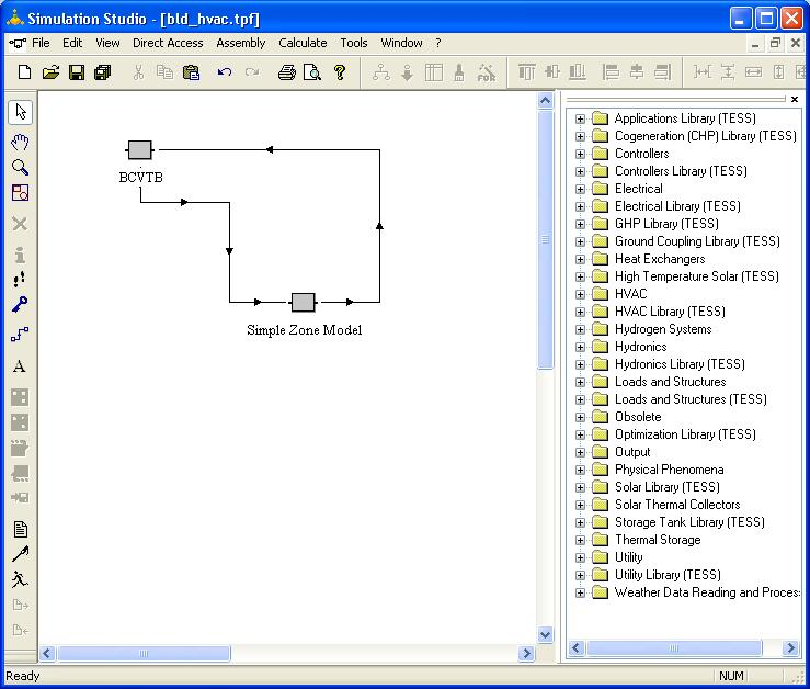
Start the TRNSYS Simulation Studio and open the bld_hvac example project (see Figure 5.27) This simple project contains two components: the BCVTB component which controls the communication between TRNSYS and BCVTB and a simple building component which takes control signals as inputs and calculates the resultant zone temperatures.
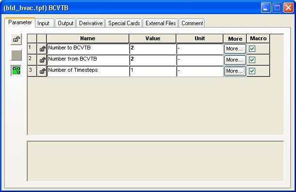
The BCVTB component (Type 6666) controls how the variables are communicated between TRNSYS and the BCVTB. There are 3 parameters: the number of variables passed to the BCVTB, the number of variables received from the BCVTB, and the number of TRNSYS timesteps per data exchange with the BCVTB. By double clicking the icon for the BCVTB component the window for setting these parameters is displayed (see Figure 5.28). In this example there are 2 variables passed to BCVTB (the zone temperatures), 2 variables passed back to TRNSYS (the control signals) and the data exchange occurs at every timestep.
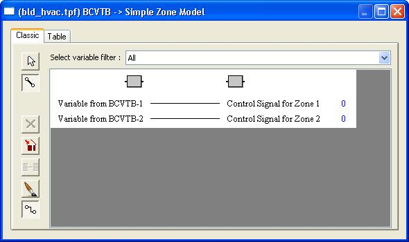
The outputs from the BCVTB component are connected to the inputs simple building component and vice versa using the usual TRNSYS linking process (see Figure 5.29 for an example).
Once the project is completed in the Simulation Studio, the dck file for the project must be created. (The BCVTB uses the dck file directly to run the TRNSYS simulation and not the Studio project file (tpf file).) The dck file is written by the pen icon on the left side of the Simulation Studio window.
To start TRNSYS from the BCVTB, you will need to create a Ptolemy II model.
The model bcvtb/examples/c-room/system-windows.xml, which is part of the BCVTB
installation and is shown in Figure 5.1, may be used as a starting point.
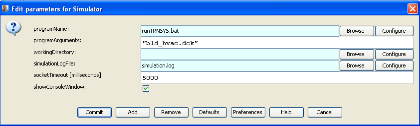
In this model, the Simulator actor will be set-up to call the actor that fires TRNSYS. Figure 5.30 shows the configuration of the Simulator actor.
The actor calls runTRNSYS.bat, with the argument bld_hvac.dck, which is the TRNSYS input file, to invoke TRNSYS.
The working directory is the current directory and the console output is written to the file simulation.log. This completes the configuration of the Ptolemy II model.
| |  | |
| 5.7. ESP-r |  | 5.9. Functional Mock-up Unit for Co-Simulation Import |