| 5.9. Functional Mock-up Unit for Co-Simulation Import | ||
|---|---|---|
 | Chapter 5. Configuring programs for use with the BCVTB |  |
| 5.9. Functional Mock-up Unit for Co-Simulation Import | ||
|---|---|---|
| | Chapter 5. Configuring programs for use with the BCVTB | |
The Functional Mock-up Unit (FMU) for co-simulation import interface allows the BCVTB to import simulation programs that are packaged as FMUs. The interface complies with the Functional Mock-up Interface standard (FMI), which is an open source standard designed to enable links between disparate simulation programs. An FMU may contain models, model description, source code, and shared libraries for multiple platforms. The FMI standard consists of three parts which are FMI for Model-Exchange, FMI for Co-Simulation, and FMI for Product Lifecycle Management. For FMI and FMU related information, we recommend to read the FMI specifications
![[Note]](images/note.png) | Note |
|---|---|
|
The FMU for co-simulation import interface supports the FMI for Co-Simulation Application Programming Interface version The FMU for co-simulation interface is supported on Windows, Linux, and Mac OS X. However it was only tested on Windows 32 bit and Linux 32 bit because of the limited support of tools capable of exporting FMU for co-simulation on Windows 64 bit, Linux 64 bit, and Mac OS X. |
To import an FMU in the BCVTB, use from the menu tab, which will prompt for a .fmu file.
After providing a valid path to an FMU, the BCVTB reads and unzips the FMU, parses the file named modelDescription.xml that describes the ports and parameters,
and creates an actor which exposes the inputs and outputs of the FMU. To change the parameters of the FMU, double-click on the actor and set the new parameters.
This example is available in the directory examples/fmu-room.
This example is the same as the example in examples/dymola-room except
that an FMU is used instead of Dymola to simulate the room model.
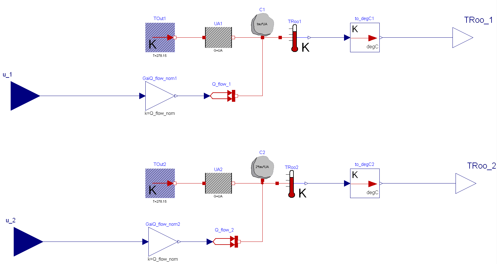
As a starting point for this example, we used the Modelica room model shown in Figure 5.13. We added connectors for input and output signals. These signals will be the inputs and outputs of the FMU which will be exposed in the Ptolemy II actor. Figure 5.31 shows the new configuration of the system model with the two inputs (u_1, u_2) and two outputs signals (TRoo_1, TRoo_2). Next, we exported the Modelica model as an FMU. This step is tool specific and is typically described in the user manual of the tool which is used to export the FMU for co-simulation.
| Note |
|---|---|
|
The Modelica model used to generate the FMU is provided in
The FMU used in the example is provided in |
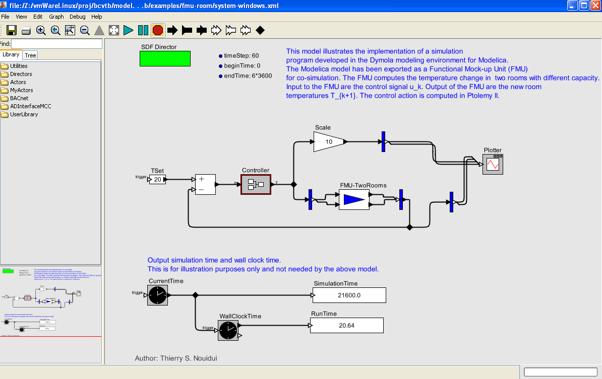
To simulate the FMU, a Ptolemy II system model needs to be created. We used the model BCVTB/examples/dymola-room/system-windows.xml, shown in
Figure 5.15 as a starting point. We replaced the Simulator actor with the imported FMU, and connected the input and output signals of the FMU with the corresponding variables in Ptolemy II. Figure 5.32 shows the configuration of the system model.
Figure 5.32. Ptolemy II system model that links a model of a controller with the FMU for co-simulation.
| |  | |
| 5.8. TRNSYS |  | 5.10. Custom program using a system command |