| 4.6. Simulink | ||
|---|---|---|
 | Chapter 4. Configuring programs for use with the BCVTB |  |
To configure Simulink, you may modify an example such as
the one in the directory
BCVTB/examples/simulink-room, or you may
create a new Simulink model. This section describes the
latter, which consists of creating a Simulink block
diagram, a MATLAB script and a Ptolemy II model.
To create a new Simulink block diagram, proceed as follows:
First, set the path to the Simulink library for the BCVTB: On the MATLAB prompt, type
addpath([getenv('BCVTB_HOME'), '/lib/matlab']);
Open Simulink and select File -> New.
Then, in the Simulink Library Browser, select the BCVTB
library.
Drag and drop the BCVTB block into your Simulink flow chart. In the Simulink flow chart, open the BCVTB block which should show this model:
In this model, the block socketIO
implements the communication with the BCVTB. It
typically need not be modified. However, you will need
to open the block selector to adjust the
field called Index in the input form shown
in
Figure 4.17
. This field specifies which elements of the input
vector should be selected and used as an output of this
block. For example, if we were to require three values,
then the field Index needs to be [1 2
3] to select the first, second and third element
of the input vector. Entering each element of the vector
is inconvenient if a large number of elements needs to
be received. In this situation, one can enter, for
example, linspace(1,50,50) to retrieve a
vector with 50 elements.
In
Figure 4.17
, the field Input port size denotes the
size of the input vector. It typically need not be
changed unless you changed the file
bcvtb/lib/defines.h.
Next, the sampling time step needs to be set. In this
example, we assume that the Simulink simulation needs to
be run with a fixed time step of 120 seconds. To
implement this configuration, select Simulation
-> Configuration Parameters... and configure
the input form as shown in
Figure 4.18
. Note that we set the stop time to inf
since Simulink will receive from the BCVTB interface a
signal when the final time is reached. We also set the
step size to 120, which is equal to the
time step in seconds that will, in this example, be used
in the Ptolemy II model.
The BCVTB block can now be connected to a model that
processes the output from the BCVTB block
and produces new input for the BCVTB block.
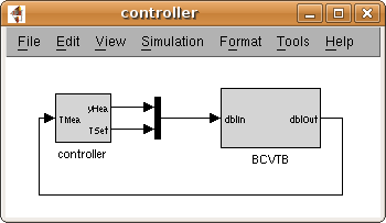
Such an implementation can be found in the model
BCVTB/examples/simulink-room/controller.mdl,
which is shown in
Figure 4.19
.
Figure 4.19. Simulink block diagram that links the controller with the block that communicates with Ptolemy II.

To perform a simulation, the BCVTB will call a MATLAB
script that adds the path of the BCVTB library to the
MATLAB path and then simulates the above model. To
create the MATLAB script, save the following three lines
in a file called simulateAndExit.m:
addpath([getenv('BCVTB_HOME'), '/lib/matlab']);
sim('controller');
quit;
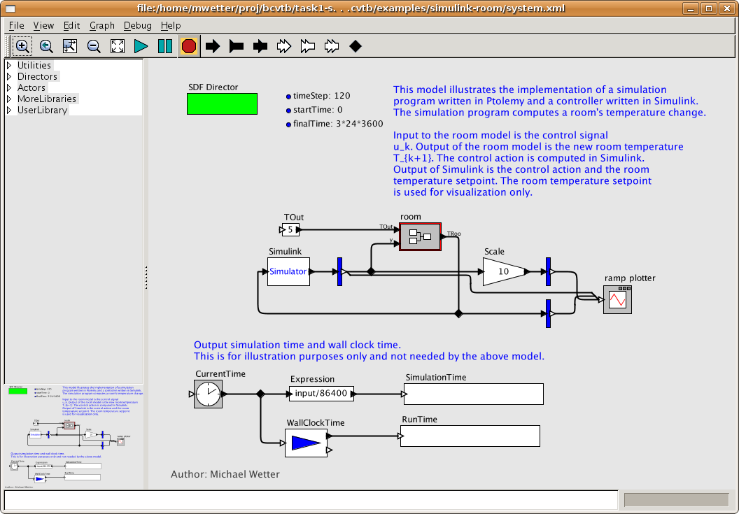
To start Simulink from Ptolemy II, a Ptolemy II model
needs to be created. The model
BCVTB/examples/simulink-room/system.xml
that is shown in
Figure 4.20
may be used as a starting point.
Figure 4.20.
Ptolemy II system model that links the Simulator actor that communicates with MATLAB with an actor that computes the room temperature and with an actor that plots the results as the simulation progresses.

In this model, the Simulator actor that
calls Simulink is configured as shown in
Figure 4.21
.
This completes the configuration.